Cooling water channel structure of automobile engine cooling fan mold

A technology for an automobile engine and a cooling water circuit, which is applied in the field of cooling water circuit structure, can solve problems such as the adverse effect of injection molding production efficiency, the insignificant cooling effect of fan blades, and the inability of the curved surface shape of fan blades to reach the desired ideal shape, etc., so as to improve performance. , good cooling effect

Pending Publication Date: 2019-03-19
NINGBO TIANLONG ELECTRONICS
View PDF0 Cites 1 Cited by
  • Summary
  • Abstract
  • Description
  • Claims
  • Application Information

AI Technical Summary

Problems solved by technology

[0004] The cooling waterway structure in the existing automobile engine cooling fan mold is composed of the fixed mold side direct waterway arranged on the periphery of the fixed mold cavity of the product and the movable mold side straight waterway arranged on the periphery of the product movable mold cavity. This cooling waterway structure has the following Problems: 1) The cooling effect on the injection-molded fan blades is not obvious, resulting in the curved surface shape of the injection-molded fan blades failing to achieve the desired ideal shape; 2) The injection molding cycle takes 75 seconds, which brings about the improvement of injection molding production efficiency adversely affected

Method used


Image

  • Cooling water channel structure of automobile engine cooling fan mold
  • Cooling water channel structure of automobile engine cooling fan mold
  • Cooling water channel structure of automobile engine cooling fan mold

Examples


Embodiment Construction

[0035] The present invention will be further described in detail below with reference to the embodiments of the accompanying drawings.

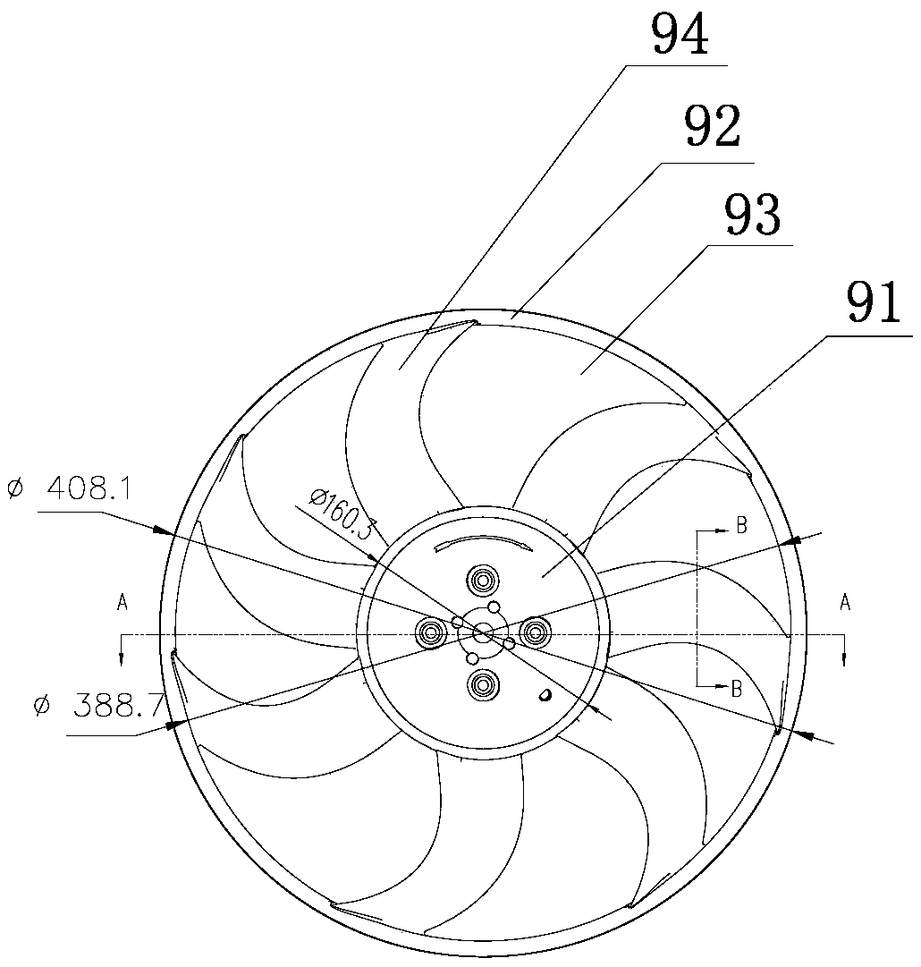
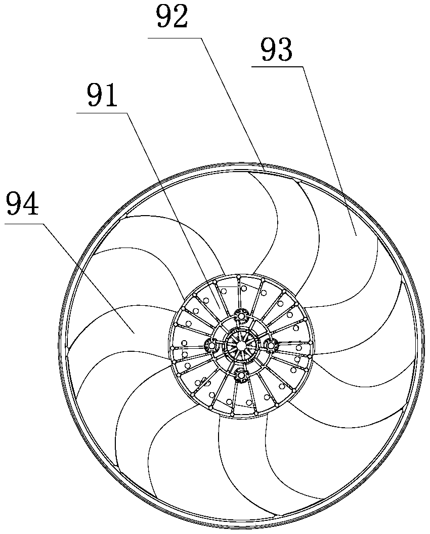
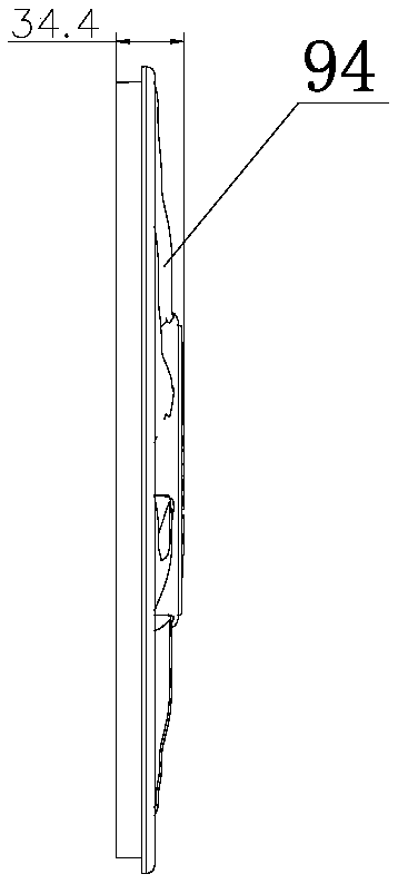
[0036] The cooling water channel structure in a kind of automobile engine cooling fan mold that the present invention proposes, such as Figure 2 to Figure 9 As shown, it is composed of the fixed mold side waterway 1 arranged on the back side of the fixed mold side fan cavity 81 and the movable mold side waterway 2 arranged on the back side of the movable mold side fan cavity 82; the fixed mold side waterway 1 includes 7 The fixed mold side water well type waterway 11 that works independently, the number of the fixed mold side water well type waterway 11 is the same as the number of blade cavities 811 in the fixed mold side fan cavity 81, and each fixed mold side water well type waterway 11 is arranged on the fixed mold side On the back side of a blade cavity 811 in the side fan cavity 81, each fixed mold side water well type waterway 11 has ...


PUM


Abstract

The invention discloses a cooling water channel structure of an automobile engine cooling fan mold. The cooling water channel structure is composed of a fixed mold side water channel arranged on the back side of a fixed mold side fan mold cavity and a movable mold side water channel arranged on the back side of a movable mold side fan mold cavity. The fixed mold side water channel comprises a plurality of independent fixed mold side well type water channels. Each fixed mold side well type water channel is arranged on the back side of a blade cavity in the fixed mold side fan mold cavity. Eachfixed mold side well type water channel is provided with an inlet and an outlet. The movable mold side water channel comprises a plurality of independent movable mold side well type water channels. Each movable mold side well type water channel is arranged on the back side of a blade cavity in the movable mold side fan mold cavity. Each movable mold side well type water channel is provided with aninlet and an outlet. The cooling water channel structure has the advantages that the cooling effect is good; the shape of the curved surface of each injection molded fan blade can reach the expectedideal shape; the injection molding period can be shortened; and the injection molding production efficiency is greatly improved.

Description

technical field [0001] The invention relates to a design and manufacturing technology of a plastic mold, in particular to a cooling water channel structure in a cooling fan mold of an automobile engine. Background technique [0002] The structure of the existing automobile engine cooling fan is as follows: Figure 1a to Figure 1e As shown, it includes a central round platform 91 and a fan spoke 92, and the annular cavity between the central round platform 91 and the fan spoke 92 is a blade installation cavity 93, and multiple fan blades 94 with different shapes are installed in the blade installation cavity 93. The distribution of fan blades 94 is uneven, and the shape of fan blades 94 is the curved surface shape of space (from Figure 1d and Figure 1e can be seen in). Common automotive engine cooling fans are made of PA66-GF30, which is a PA66 material containing 30% glass brazing, with an outer diameter of 408.1mm and a thickness of 34.4mm. It is 388.7m, and seven fan ...

Claims


Application Information

Patent Timeline
IPC IPC(8): B29C45/73
CPCB29C45/7312
Inventor 张劲松刘宝升王元挺赖久乐于忠灿
Owner NINGBO TIANLONG ELECTRONICS
Why Eureka
Try Eureka