
A foot device for assisting weight-bearing lower extremity exoskeleton

An exoskeleton and foot technology, applied in the direction of program-controlled manipulators, manufacturing tools, manipulators, etc., can solve the problems of reducing user comfort, impacting the spine and brain, and impact, etc., so as to increase the contact area of ​​the sole of the foot and reduce the size of the foot. Bottom pressure value, the effect of reducing human torque

Inactive Publication Date: 2021-08-31
HEBEI UNIV OF TECH
View PDF9 Cites 0 Cited by
  • Summary
  • Abstract
  • Description
  • Claims
  • Application Information

AI Technical Summary

Problems solved by technology

[0003] Existing exoskeletons often work under heavy loads, and when the feet touch the ground, there will be a large impact, and the feet will definitely feel tired, reducing the comfort of the user, unable to maintain speed and endurance, and impacting the spine at the same time and brain, damage to health, and the impact reduces productivity
At present, the foot structure of the exoskeleton at home and abroad is only one plate, which will produce a large impact when it comes into contact with the ground. None of them involve the comfort of the foot joints, and the design of the foot is not perfect.

Method used


Image

  • A foot device for assisting weight-bearing lower extremity exoskeleton
  • A foot device for assisting weight-bearing lower extremity exoskeleton
  • A foot device for assisting weight-bearing lower extremity exoskeleton

Examples


Embodiment Construction

[0026] Specific examples of the present invention are given below. The specific embodiments are only used to further describe the present invention in detail, and do not limit the protection scope of the claims of the present application.

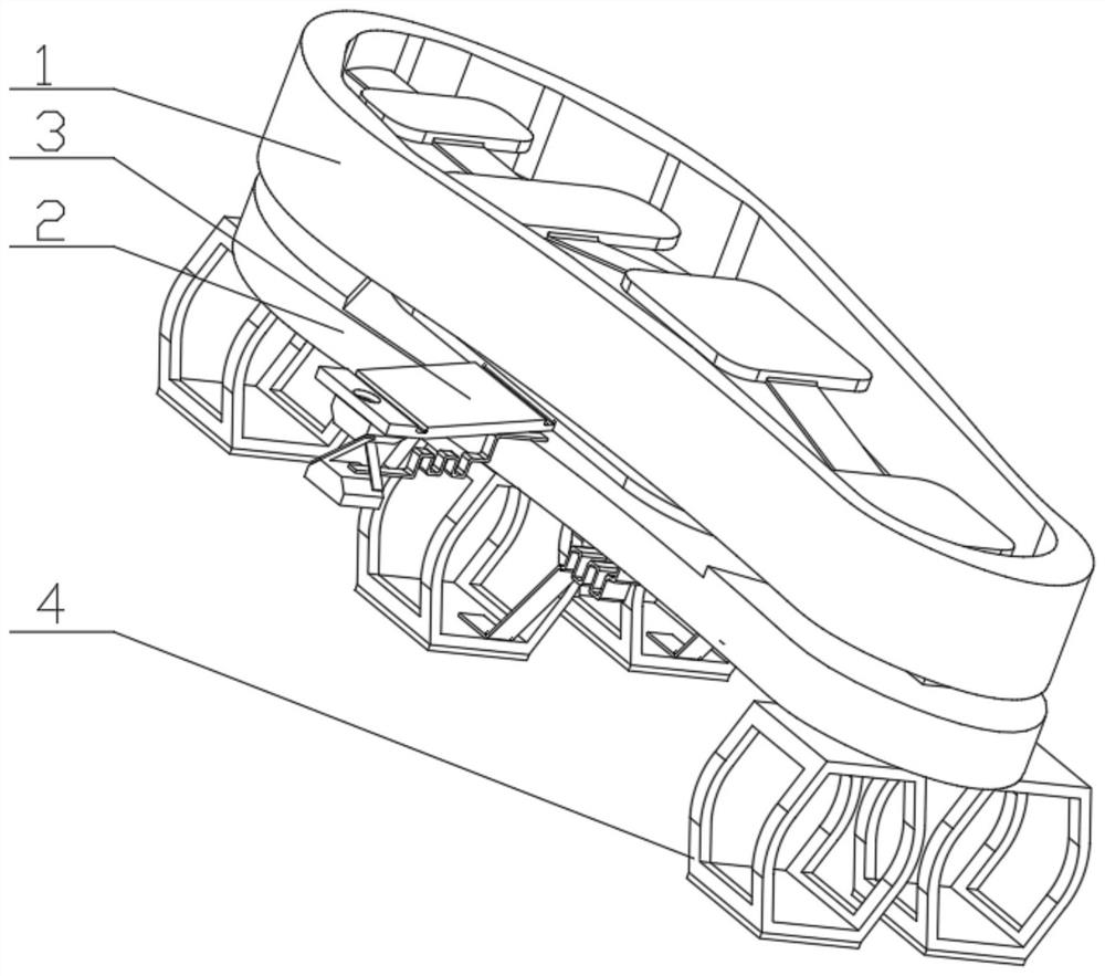
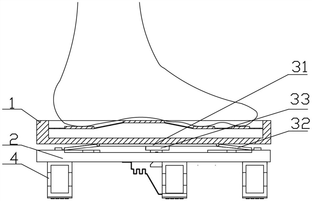
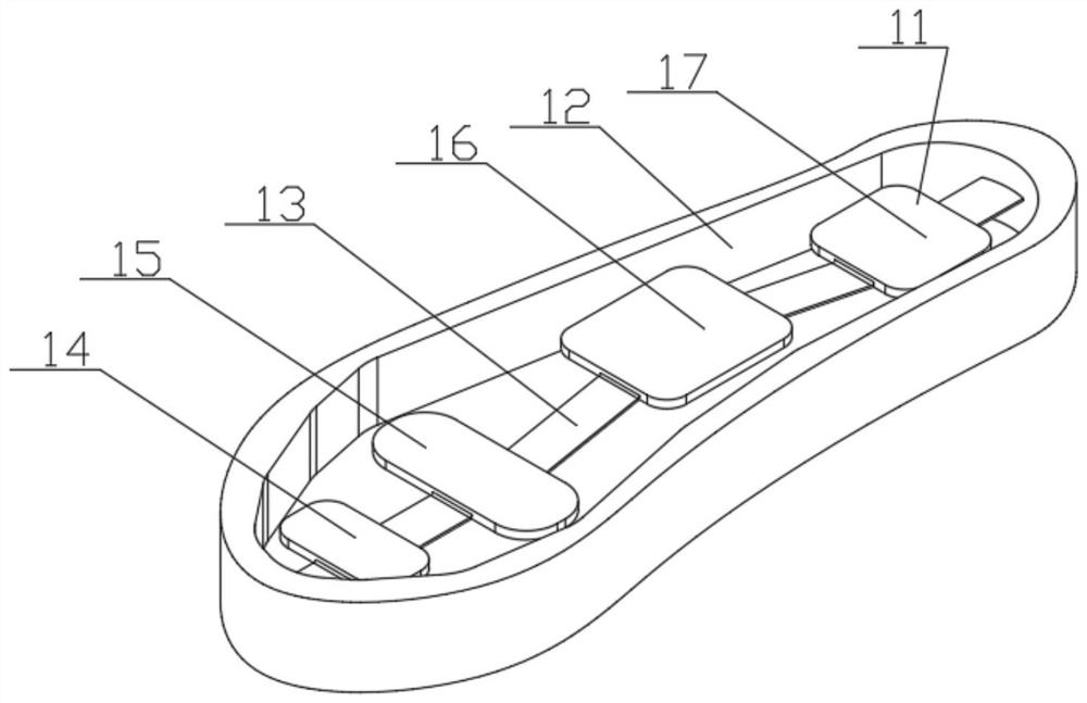
[0027] The invention provides a foot device (foot device for short, refer to Figure 1-8 ), characterized in that the foot device includes a contact plate 1, a support plate 2, a human body arch mechanism 3 and an elastic damping mechanism 4; the human body arch mechanism 3 is arranged between the contact plate 1 and the support plate 2, respectively The contact plate 1 is connected with the support plate 2; the contact plate 1 is used to completely contact with the human foot, fully release the degree of freedom of the sole of the foot during walking, and increase the walking comfort; the human foot arch mechanism 3 can imitate the human longitudinal arch and The transverse bow moderates impact and vibration, absorbs energy when stressed,...


PUM


Abstract

The invention discloses a foot device for assisting a load-bearing lower limb exoskeleton, comprising a contact plate, a support plate, a human foot arch mechanism and an elastic damping mechanism; the contact plate is used to completely contact with the human foot; the human foot arch mechanism is arranged on Between the contact plate and the support plate, they are respectively connected to the contact plate and the support plate for simulating the cushioning force of the arch of the human foot; the elastic damping mechanism is installed on the lower surface of the support plate for increasing the elastic damping of the foot device. The human foot arch mechanism includes an elastic connecting plate, a longitudinal arch unit and a transverse arch unit; the elastic connecting plate is located at the center of the upper surface of the support plate; the longitudinal arch unit connects the elastic connecting plate and the supporting plate longitudinally to realize the simulation of the longitudinal arch of the foot; the transverse arch The unit laterally connects the elastic connecting plate and the support plate to simulate the transverse arch of the foot. The problem that the foot device of the auxiliary load-bearing lower extremity exoskeleton is in contact with the ground to generate a large impact and reduce work efficiency is solved.

Description

technical field [0001] The invention relates to the field of robot exoskeleton, in particular to a foot device for assisting load-bearing lower extremity exoskeleton. Background technique [0002] Since the beginning of the 21st century, scientific research on humanoid robots has become a popular research direction in the field of robotics research. All over the world, different scientific research institutions have developed various types of humanoid robots with different uses, and they play a pivotal role in assisting or replacing human beings in life and production. However, it is accompanied by many problems in actual use. For example, robots are operated and executed by previously set programs, and they cannot predict, and cannot adapt to emergencies like humans, so it is difficult to mass-produce them in large areas and put them into practical use. In order to overcome this problem, some scientists have proposed a wearable robot that can rely on human limbs and joint...

Claims


Application Information

Patent Timeline
Patent Type & Authority Patents(China)
IPC IPC(8): B25J9/00
CPCB25J9/0006
Inventor 张建军栾益鹏李潇王麟解永刚孟令聪
Owner HEBEI UNIV OF TECH
Learn More