Waterproof high-voltage cabinet

A high-voltage cabinet, waterproof technology, applied in the field of substations, can solve the company's power failure, the inability to recycle the land, the damage of high-voltage cabinet components and other problems, and achieve the effect of preventing electrical components from being damaged.

Pending Publication Date: 2019-03-15
黄建国
View PDF0 Cites 1 Cited by
  • Summary
  • Abstract
  • Description
  • Claims
  • Application Information

AI Technical Summary

Problems solved by technology

Although enterprises or factories can prevent floods when considering site selection, with changes in the natural environment, some factories, enterprises or companies may still be attacked by floods, and some high-voltage cabinets cannot better protect against floods. , the flood penetrates into the interior of the high-voltage cabinet, which will damage the internal components of the high-voltage cabinet and cause the loss of the company's assets
Secondly, the infiltration of flood water into the high-voltage cabinet will cause the company to have a power outage, and the inability of the high-voltage cabinet to work continuously underwater will cause the company to lack power supply in terms of flood control, which will cause some assets of the factory, enterprise or company to be irretrievable
Existing high-voltage cabinets are often installed individually. When a factory, enterprise or company is running, it is necessary to purchase multiple high-voltage cabinets. The purchased single high-voltage cabinet is installed independently, and the high-voltage station occupies an increased area, making it impossible for the factory, enterprise or company to resource land use

Method used


Image

  • Waterproof high-voltage cabinet
  • Waterproof high-voltage cabinet
  • Waterproof high-voltage cabinet

Examples


Embodiment 1

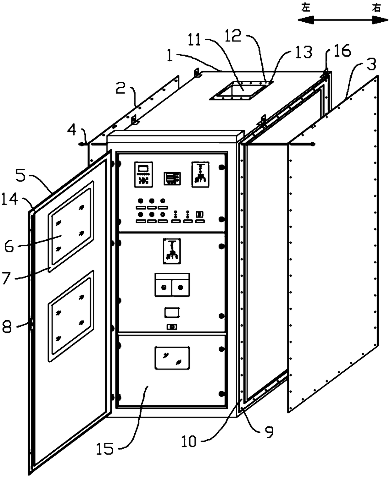
[0034] Such as figure 1 As shown, in this embodiment, the present invention includes:

[0035] Cabinet 1, the front, left and right sides of the cabinet 1 are provided with openings, the cabinet 1 is provided with a cavity for accommodating electrical components and the bottom of the cabinet 1 is provided with a A cable sealing device that achieves a waterproof effect on the cable, a control panel 15 is provided inside the cabinet 1, and the control panel 15 is vertically arranged at the opening on the front side of the cabinet 1, and the control panel 15 The periphery is sealed and fixedly connected with the inner wall of the cabinet body 1; the bottom of the cabinet body 1 is provided with a cable inlet hole, and the cable sealing device is arranged in the cable inlet hole for connecting the cable with the cabinet body 1 to form a seal, the cable sealing device includes a shell, a cover plate and a sealing sleeve, the shell includes a shell main body, an extension body and ...

Embodiment 2

[0041] Such as figure 2As shown, in this embodiment, there are three cabinets 1 of the present invention, and the content is the same as that of the first embodiment. The four cabinets 1 are respectively a cabinet 1A, a cabinet 1B and a cabinet 1C, and the cabinet 1A, the cabinet 1B and the cabinet 1C are sequentially connected in series to form a closed body, and the left sealing plate 2 is fixed by a fixing rod 4 On the left side of the cabinet body 1C, the right sealing plate 3 is fixed on the right side of the cabinet body 1A through a fixing rod 4, and the forced ventilation opening 11 of the cabinet body 1C is fixed with an air intake port by bolts. Pipe 18, the forced ventilation opening 11 of the cabinet body 1A is fixed with an air outlet pipe 19 by bolts, the forced ventilation opening 11 of the cabinet body 1B is fixed with a blind plate 17 through bolts, and the air inlet pipe 18 And the air outlet pipe 19 makes the heat generated by the electrical components in ...

Embodiment 3

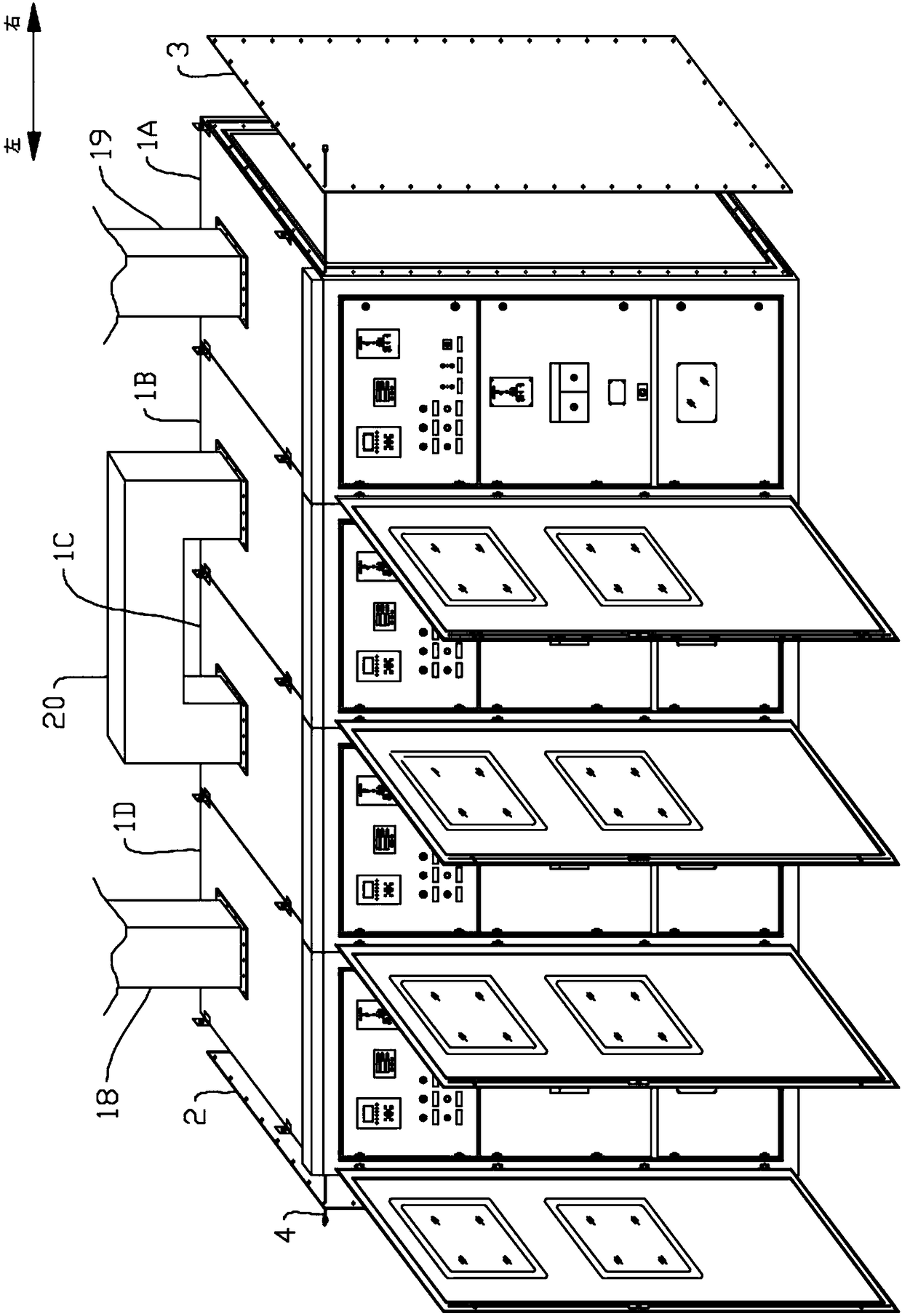
[0043] Such as image 3 As shown, in this embodiment, there are four cabinets 1 of the present invention, and the content is the same as that of the first embodiment. The four cabinets 1 are respectively cabinet 1A, cabinet 1B, cabinet 1C and cabinet 1D, and cabinet 1A, cabinet 1B, cabinet 1C and cabinet 1D are sequentially connected in series to form a closed body, and the left The sealing plate 2 is fixed on the left side of the cabinet 1D through the fixing rod 4, the right sealing plate 3 is fixed on the right side of the cabinet 1A through the fixing rod 4, and the forced ventilation port of the cabinet 1D 11 is fixed with an air inlet pipe 18 by bolts, and the forced ventilation port 11 of the cabinet body 1A is fixed with an air outlet pipe 19 by bolts, and the forced ventilation port 11 of the cabinet body 1B and the cabinet body An air duct 20 is provided between the forced ventilation openings 11 of 1C, and the two ends of the air duct 20 are respectively fixed on t...


PUM

PropertyMeasurementUnit
Thicknessaaaaaaaaaa

Abstract

The invention relates to a waterproof high-voltage cabinet, and the cabinet comprises a cabinet body. The interior of the cabinet body is provided with a cavity for accommodating an electrical element. The interior of the cabinet body is provided with a control panel, and the control panel enables a cavity to be divided into two independent cavities. A plurality of cabinet splicing holes are circularly set at intervals along the edge of a side wall of the cabinet body, and laterally pass through the cabinet body. The left and right sides of the cabinet body are respectively provided with a left sealing plate for sealing the left side of the cabinet body and a right sealing plate for sealing the right side of the cabinet body. The fixed rods are set to be corresponding to the cabinet splicing holes, and sequentially pass through the left sealing plate, the cabinet splicing holes and the right sealing plate. The fixed rods enable the left and right sealing plates to be respectively fixedat the left and right side of the cabinet body. The cabinet door is disposed at the front side of the cabinet body, and is used for forming a sealed cavity with a control panel through enclosing. Oneside of the cabinet door is hinged to the cabinet body. A forced ventilation port is disposed at the top of the cabinet body and is used for forcing the ventilation of the cavity in the cabinet body.The cabinet provided by the invention can achieve the splicing assembly while achieving the waterproof effect.

Description

technical field [0001] The invention relates to the technical field of substations, in particular to a waterproof high-voltage cabinet. Background technique [0002] With the application of various substations in various places, especially in enterprises, factories or companies that use high-voltage electricity, a large number of high-voltage cabinets will be used. Although enterprises or factories can prevent floods when considering site selection, with changes in the natural environment, some factories, enterprises or companies may still be attacked by floods, and some high-voltage cabinets cannot better protect against floods. , flood penetration into the interior of the high-voltage cabinet will damage the internal components of the high-voltage cabinet, resulting in the loss of the company's assets. Secondly, the infiltration of flood water into the high-voltage cabinet will cause the company to have a power outage. The inability of the high-voltage cabinet to work con...

Claims


Application Information

Patent Timeline
IPC IPC(8): H02B1/56H02B1/30H02B1/28
CPCH02B1/28H02B1/30H02B1/565
Inventor 黄建国
Owner 黄建国
Why Eureka
Try Eureka