
Plate cutting device capable of collecting chippings conveniently

A cutting device and chip technology, applied in bark area/chips/dust/waste removal, sawing equipment, wood processing appliances, etc., can solve the problems of loud noise, troublesome cleaning, scattered wood chips, etc., to achieve accurate cutting , Reduce the effect of cleaning characters

Inactive Publication Date: 2019-03-15
嘉善顺源金属制品有限公司
View PDF6 Cites 10 Cited by
  • Summary
  • Abstract
  • Description
  • Claims
  • Application Information

AI Technical Summary

Problems solved by technology

[0002] Before the production of various products, the board needs to be cut to a suitable size according to the processing needs. In the existing equipment, traditional cutting devices such as electric saws are usually used to cut the board. Since the cutting process is in the open air and Without protective measures, the sawdust generated during the cutting process is scattered. Not only is it troublesome to clean, but also the smaller sawdust is inhaled by the staff, which will cause physical discomfort and affect the physical and mental health of the staff. There is no isolation board during the cutting process. The noise generated by cutting is relatively loud, and the long-term presence of staff in a noisy environment will affect their hearing, and cause dizziness, which will seriously cause deafness and life-threatening. Therefore, it is urgent to develop a plate cutting device. overcome the above problems

Method used


Image

  • Plate cutting device capable of collecting chippings conveniently
  • Plate cutting device capable of collecting chippings conveniently
  • Plate cutting device capable of collecting chippings conveniently

Examples


Embodiment Construction

[0023] The following will clearly and completely describe the technical solutions in the embodiments of the present invention with reference to the accompanying drawings in the embodiments of the present invention. Obviously, the described embodiments are only some, not all, embodiments of the present invention. All other embodiments obtained by persons of ordinary skill in the art based on the embodiments of the present invention belong to the protection scope of the present invention.

[0024] According to an embodiment of the present invention, there is provided a plate cutting device that facilitates debris collection.

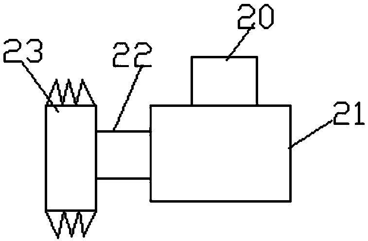
[0025] Such as Figure 1-4 As shown, according to an embodiment of the present invention, a plate cutting device that is convenient for collecting debris includes a workbench 1, and legs 12 are arranged at the corners of the bottom end of the workbench 1, and the bottom ends of the legs 12 are each A telescopic rod 13 is provided, and a spring 14 is arran...


PUM


Abstract

The invention discloses a plate cutting device capable of collecting chippings conveniently. The plate cutting device comprises a workbench. Support legs are correspondingly arranged at the corners ofthe bottom end of the workbench. First telescopic rods are correspondingly arranged at the bottom ends of the support legs. First springs are correspondingly arranged on the outer sides of the firsttelescopic rods. A chipping collecting port is formed in the middle part in the workbench. A chipping collecting pipe is arranged at the bottom end of the chipping collecting port. A fan is arranged at one side of the chipping collecting pipe. A chipping collecting box is arranged on the side away from the fan and on one side of the chipping collecting pipe. An air exhaust pipe is arranged on theside away from the chipping collecting pipe and on one side of the chipping collecting box. A bottom cover is arranged at the bottom end of the chipping collecting box. The side, at the same side as the air exhaust pipe, of the bottom cover is connected with the chipping collecting box through a sixth connecting shaft. A fourth fixing block is arranged on the one side of the bottom end of the chipping collecting box and the side away from the sixth connecting shaft, a fourth connecting shaft is arranged in the middle of the fourth fixing block, a fixing rod is arranged on the fourth connectingshaft, the fixing rod is in an L shape, and grooves are symmetrically formed in the two sides of the top end of the chipping collecting port and positioned in the top end of the workbench.

Description

technical field [0001] The invention relates to the technical field of cutting, in particular to a plate cutting device which is convenient for collecting debris. Background technique [0002] Before the production of various products, the board needs to be cut to a suitable size according to the processing needs. In the existing equipment, traditional cutting devices such as electric saws are usually used to cut the board. Since the cutting process is in the open air and Without protective measures, the sawdust generated during the cutting process is scattered. Not only is it troublesome to clean, but also the smaller sawdust is inhaled by the staff, which will cause physical discomfort and affect the physical and mental health of the staff. There is no isolation board during the cutting process. The noise generated by cutting is relatively loud, and the long-term presence of staff in a noisy environment will affect their hearing, and cause dizziness, which will seriously c...

Claims


Application Information

Patent Timeline
IPC IPC(8): B27B5/06B27B5/22B27B5/29B27G3/00B27G19/02
CPCB27B5/06B27B5/22B27B5/29B27G3/00B27G19/02
Inventor 龚小飞
Owner 嘉善顺源金属制品有限公司
Learn More