
Pipe welding device for building construction

A welding device and building construction technology, applied in auxiliary devices, welding equipment, auxiliary welding equipment, etc., can solve the problems of missing welding, easy fracture of pipes when turned over, and welding bumps, etc., to save labor costs, simple and effective structure, and device operation. stable effect

Active Publication Date: 2019-03-15
ZHEJIANG AOCHUAN HYDRAULIC
View PDF6 Cites 17 Cited by
  • Summary
  • Abstract
  • Description
  • Claims
  • Application Information

AI Technical Summary

Problems solved by technology

[0006] The object of the present invention is to provide a pipe welding device for building construction, to solve the time-consuming and laborious operation of construction workers proposed in the background technology, the construction pipes cannot be welded at one time, and partial welding, missing welding, and welding are prone to occur when rotating the construction pipes. Tumors, tubes are easy to break during turning over, etc.

Method used


Image

  • Pipe welding device for building construction
  • Pipe welding device for building construction
  • Pipe welding device for building construction

Examples


Embodiment 1

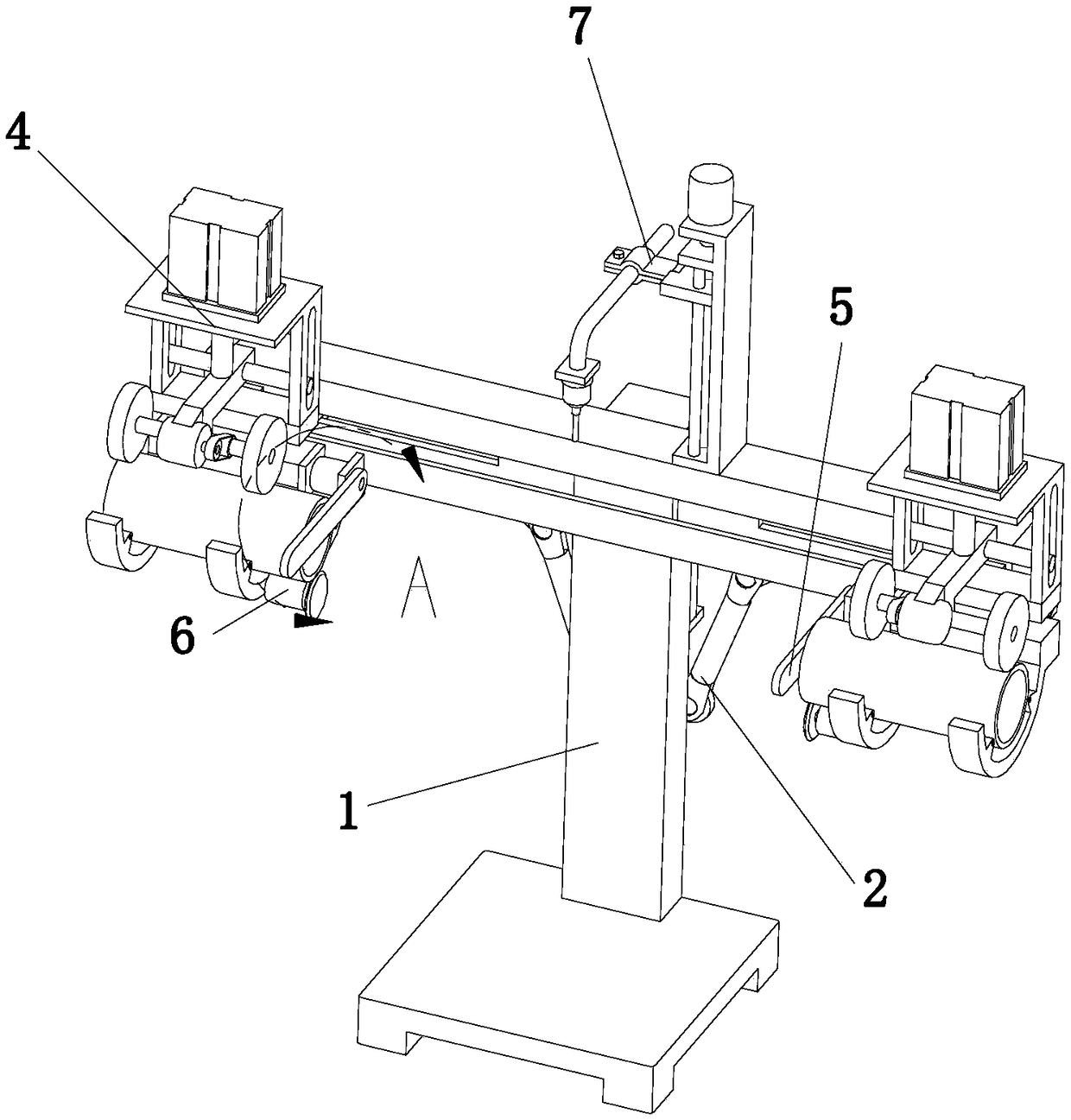
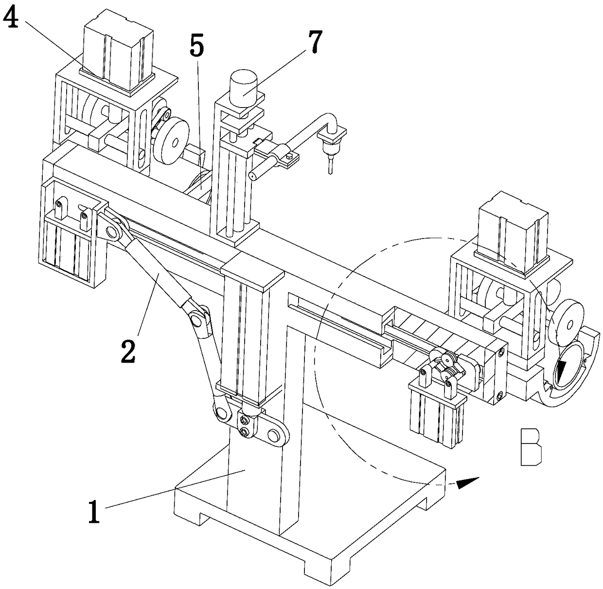
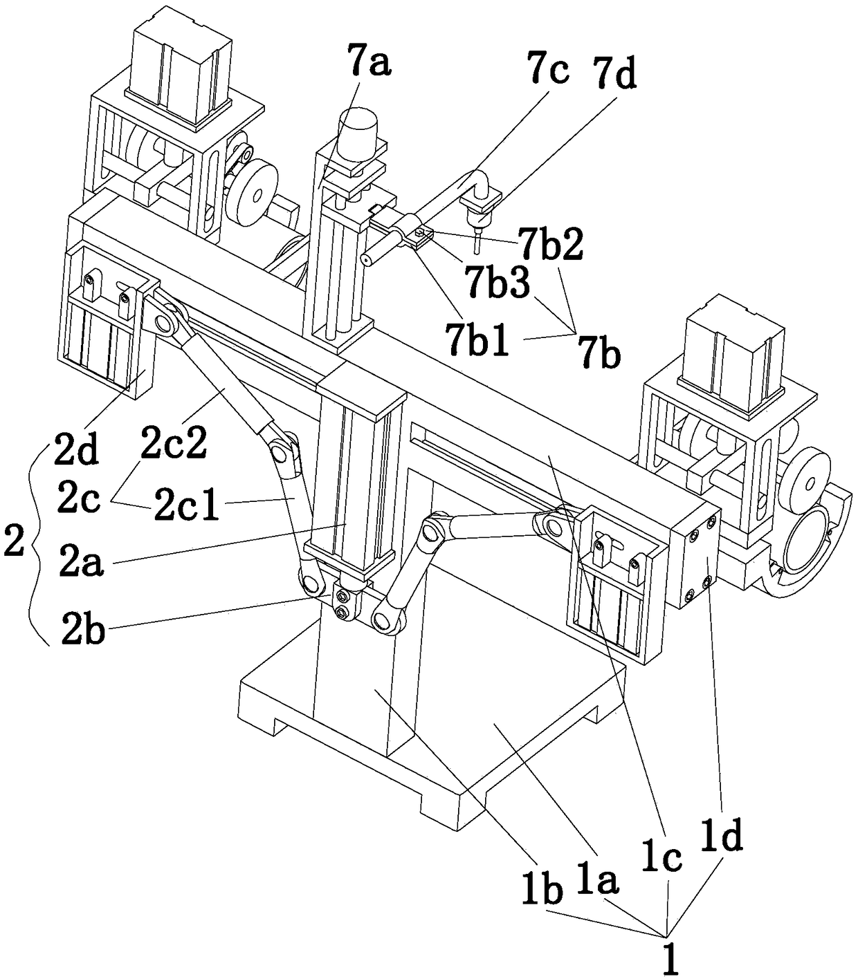
[0037] The invention provides a pipe welding device for building construction, such as Figure 1-Figure 7 As shown, it includes a T-shaped frame 1, a synchronous moving device 2, a fixing device 3, a clamping device 4, a positioning device 5, a trimming device 6, and a welding device 7. The T-shaped frame 1 includes a base 1a, a column 1b, and a beam Track 1c and sealing end 1d, the column 1b is installed on the base 1a, the beam track 1c is horizontally installed on the column 1b, the sealing end 1d is installed at both ends of the beam track 1c, and the synchronous moving device 2 is arranged on On the column 1b, the two fixing devices 3 are arranged on both sides of the column 1b and are connected in transmission with the synchronous moving device 2, and the synchronous moving device 2 can drive the two fixing devices 3 to face each other along the beam track 1c Or relatively synchronous movement, the clamping device 4 is arranged on both sides of the beam track 1c, two cla...

Embodiment 2

[0050] Another scheme after the improvement of the pipe welding device used for building construction of the present invention is as follows, it is a kind of scheme that can be easily moved, as Figure 8 , which includes a guide rail 8a used in conjunction with the base 1a. The guide rail 8a is fixedly installed on the workshop floor. A through groove 8e is provided on the extension part 8c; a plurality of universal balls 8d are set on the top surface of the convex strip 8b, the base 1a can slide on the convex strip 8b, and the universal ball 8d can reduce the frictional force during sliding; the base There are two lockable bolt assemblies 8f on 1a, and the bolt assemblies 8f can slide in the through groove 8e at the same time. When the base 1a moves to a suitable position, the bolt assemblies 8f are locked, and the base 1a and the guide rail 8a are integrated , so that the pipe welding device is in a reasonable position. The advantage of this scheme is that the whole pipe we...


PUM


Abstract

The invention relates to the field of building construction equipment, in particular to a pipe welding device for building construction, comprising a T-shaped frame, a synchronous moving device, fixing devices, clamping devices, positioning devices, trimming devices and a welding device, wherein the synchronous moving device is arranged on the T-shaped frame, the fixing devices are arranged on both sides of the T-shaped frame and are connected with the synchronous moving device, the clamping devices are arranged on both sides of a beam guide rail, the clamping devices are connected with the fixing devices, and the fixing devices move to drive the clamping devices along the beam guide rail to do synchronized motion, the positioning devices are disposed on the sides of the two clamping devices near columns, the trimming devices are disposed on the sides of the clamping devices near the columns, and the welding device is installed above the middle of the beam guide rail. The invention canrealize the automatic welding of the pipe, realize the automatic alignment of the pipe welding part, can prevent the construction pipe material from being broken at the welded part during the rotation process, effectively reduce the labor intensity of the construction worker, and ensure the construction progress and the construction quality.

Description

technical field [0001] The invention relates to the field of building construction equipment, in particular to a pipe welding device for building construction. Background technique [0002] As an indispensable support and transmission material in the construction field, pipes are widely used in the construction field. Usually, in order to meet the needs of construction and use, the length of the pipe needs to be changed. Usually, the pipe has a fixed length when purchased from the manufacturer. Therefore, during use, the length of the pipe needs to be adjusted, which is too long compared to the required length. When cutting is required, with the help of pipe cutting equipment, and when the length is too short compared to the required length, welding is required. [0003] In the prior art, when welding construction pipes, it is necessary to manually grind the welding parts of the two construction pipes, and then align the welding parts of the two construction pipes. The pipe...

Claims


Application Information

Patent Timeline
Patent Type & Authority Applications(China)
IPC IPC(8): B23K37/053B23K37/02
CPCB23K37/0247B23K37/0538
Inventor 高元琴
Owner ZHEJIANG AOCHUAN HYDRAULIC
Learn More