Improved welding head fixing device

A welding head and fixing device technology, applied in welding equipment, laser welding equipment, metal processing equipment, etc., can solve problems such as affecting the normal use of the ball screw, dislocation of the welding head of the welding head, and generating more sparks, etc. To achieve the effect of tight fixed connection, avoid dislocation, and improve service life

Inactive Publication Date: 2019-03-12
NORTH CHINA INST OF AEROSPACE ENG
View PDF6 Cites 1 Cited by
  • Summary
  • Abstract
  • Description
  • Claims
  • Application Information

AI Technical Summary

Problems solved by technology

[0002] Laser welding machine, also known as laser welding machine and laser welding machine, is a machine for laser material processing. According to its working mode, it is divided into laser mold welding machine, automatic laser welding machine, laser spot welding machine and optical fiber transmission laser welding machine. , laser welding is to use high-energy laser pulses to locally heat the material in a small area. The energy of the laser radiation diffuses to the inside of the material through heat conduction, and the material is melted to form a specific molten pool to achieve the purpose of welding. When using laser welding During the welding process, it is necessary to use the fixing device to fix the welding head. However, the fixing device has the following disadvantages when it is used: when the fixing device fixes the welding head, the shaking and movement of the fixing device will cause the welding machine to The welding spot of the head is dislocated, which affects the normal welding, and because the position of the welding head needs to be adjusted by the ball screw, the dust is easy to accumulate on the surface of the ball screw through the chute, affecting the normal use of the ball screw. Moreover, the welding head will generate more sparks during the welding process, and the splashing of sparks will cause danger to the surrounding staff. Therefore, people are in urgent need of a new and improved welding head fixing device to solve the above problems

Method used


Image

  • Improved welding head fixing device
  • Improved welding head fixing device
  • Improved welding head fixing device

Examples


Embodiment

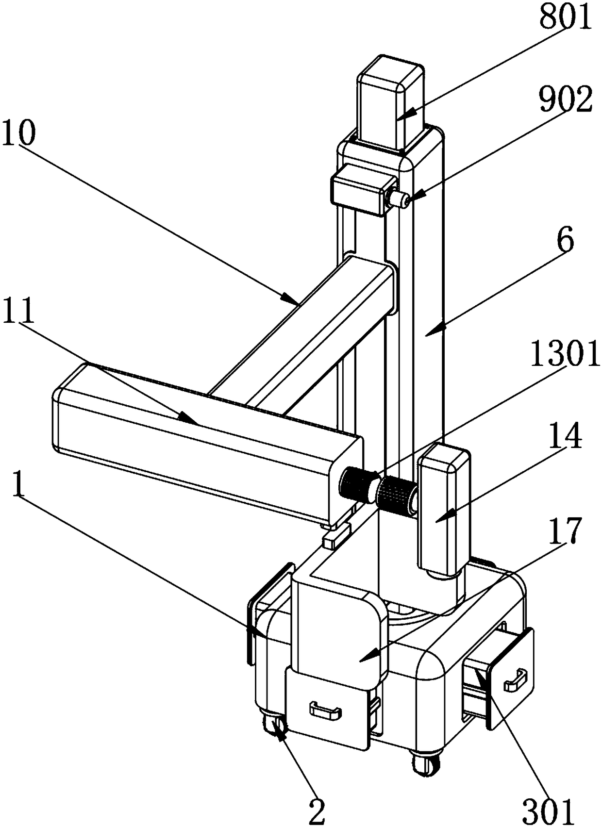
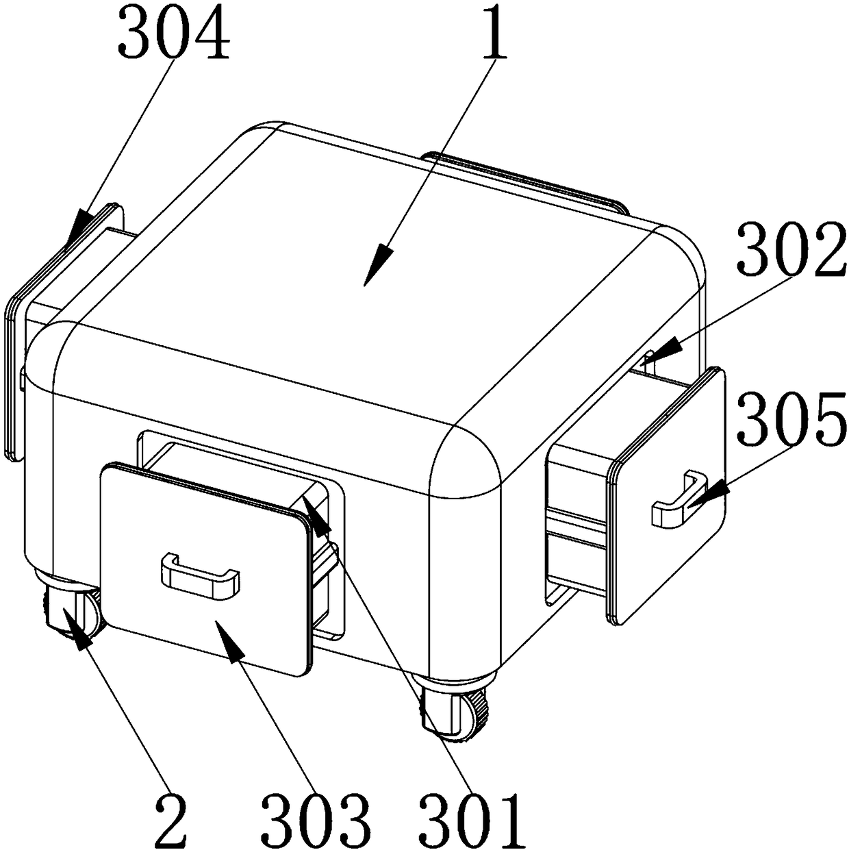
[0048] Example: such as Figure 1-11 As shown, the present invention provides a technical solution, an improved welding head fixing device, including a base 1, and the corners of the bottom of the base 1 are fixed with universal wheels 2 by fixing screws, and each side of the base 1 A counterweight assembly 3 is installed inside, and the counterweight assembly 3 includes a counterweight 301 , an installation slot 302 , an installation card 303 , a fixed rubber ring 304 and a disassembly handle 305 ;

[0049] Each side of the base 1 is embedded with a counterweight 301, and the middle of each side of the base 1 is provided with a mounting slot 302. One end of the counterweight 301 is fixed with a mounting card 303 by a fixing screw, and the side of the mounting card 303 A fixed rubber ring 304 is embedded in the upper part by glue, and a disassembly handle 305 is fixed in the middle of one side of the installation clamp 303 by fixing screws. In order to make the installation cl...


PUM


Abstract

The invention discloses an improved welding head fixing device which comprises a base. Universal wheels are arranged on vertex angles of the bottom end of the base; balance weight components are arranged on all side parts of the base; and a support assembly is arranged in the middle of the bottom end of the base. The improved welding head fixing device provided by the invention is scientific and reasonable in structure, and safe and convenient to use; through the balance weight blocks, the gravity center of the fixing device can be effectively reduced, and the occurrence of a dumping phenomenon occurred when the fixing device is used for fixing a welding head is prevented; through installation clamp slots, installation clamp plates and fixed rubber rings, the balance weight blocks and thebase can be tightly connected fixedly, so that the balance weight blocks are prevented from being separated; through support plates, antiskid rubber pads and antiskid bulge balls, the bottom end of the base can be support, and the friction force between the base and the floor is increased; and due to designing the universal wheels, the fixing device is prevented from displacing during use, the stability performance of the fixing device during use can be effectively improved, and the occurrence of the phenomenon of welding point dislocation is avoided.

Description

technical field [0001] The invention relates to the technical field of laser welding machines, in particular to an improved welding head fixing device. Background technique [0002] Laser welding machine, also known as laser welding machine and laser welding machine, is a machine for laser material processing. According to its working mode, it is divided into laser mold welding machine, automatic laser welding machine, laser spot welding machine and optical fiber transmission laser welding machine. , laser welding is to use high-energy laser pulses to locally heat the material in a small area. The energy of the laser radiation diffuses to the inside of the material through heat conduction, and the material is melted to form a specific molten pool to achieve the purpose of welding. When using laser welding During the welding process, it is necessary to use the fixing device to fix the welding head. However, the fixing device has the following disadvantages when it is used: wh...

Claims


Application Information

Patent Timeline
IPC IPC(8): B23K26/70
CPCB23K26/702
Inventor 王喜斌李国洪孙东辉杨晓东王宏宇李津宇叶昊杨超张淼宫旭泽王赛云王冠宇裴梦琴赵建鹏
Owner NORTH CHINA INST OF AEROSPACE ENG
Why Eureka
Try Eureka