
Tilt adjustment method for electric tilt antenna and corresponding device

An electronically adjustable antenna and corresponding relationship technology, which is applied to antennas, electrical components, etc., can solve the problems of insufficient adjustment of the inclination angle of the electronically adjustable antenna, affecting communication signal coverage and user experience, etc.

Active Publication Date: 2019-03-08
COMBA TELECOM TECH (GUANGZHOU) CO LTD
View PDF9 Cites 7 Cited by
  • Summary
  • Abstract
  • Description
  • Claims
  • Application Information

AI Technical Summary

Problems solved by technology

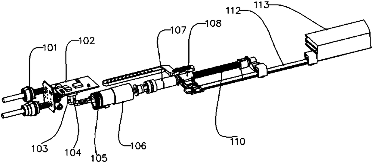
[0006] Embodiments of the present invention provide a method for adjusting the inclination angle of an electronically adjustable antenna and a corresponding device, which are used to solve the technical problems in the prior art that the inclination angle of the electronically adjustable antenna is not adjusted in place due to structural fit gaps, which affects communication signal coverage and user experience.

Method used


Image

  • Tilt adjustment method for electric tilt antenna and corresponding device
  • Tilt adjustment method for electric tilt antenna and corresponding device
  • Tilt adjustment method for electric tilt antenna and corresponding device

Examples


Embodiment Construction

[0059] In order to make the purpose, technical solutions and advantages of the embodiments of the present invention clearer, the technical solutions in the embodiments of the present invention will be clearly and completely described below in conjunction with the drawings in the embodiments of the present invention. Obviously, the described embodiments It is a part of embodiments of the present invention, but not all embodiments. Based on the embodiments of the present invention, all other embodiments obtained by persons of ordinary skill in the art without creative efforts fall within the protection scope of the present invention.

[0060] In addition, the term "and / or" in this article is only an association relationship describing associated objects, which means that there may be three relationships, for example, A and / or B, which may mean: A exists alone, A and B exist at the same time, There are three cases of B alone. In addition, the character " / " in this article, unles...


PUM


Abstract

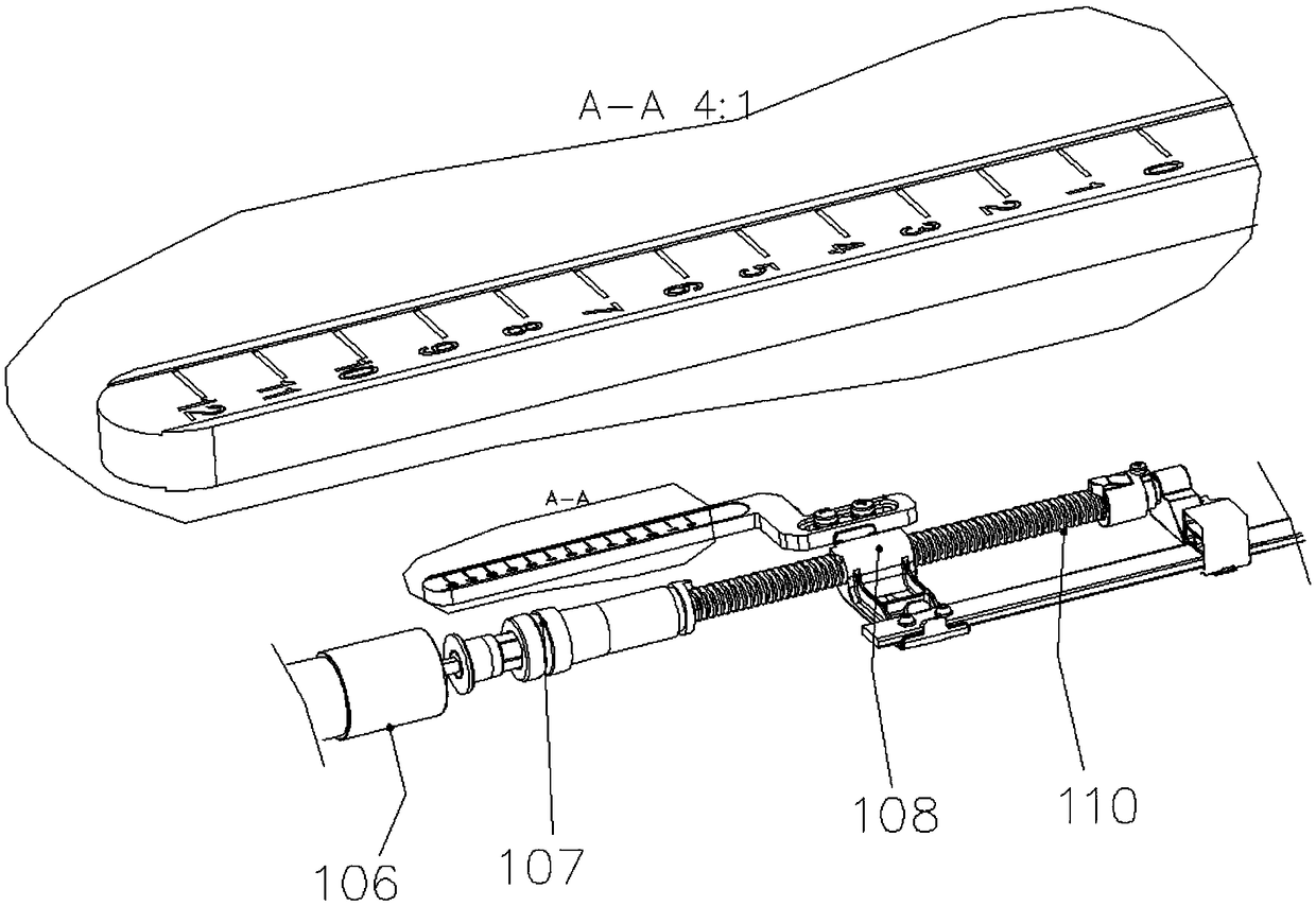
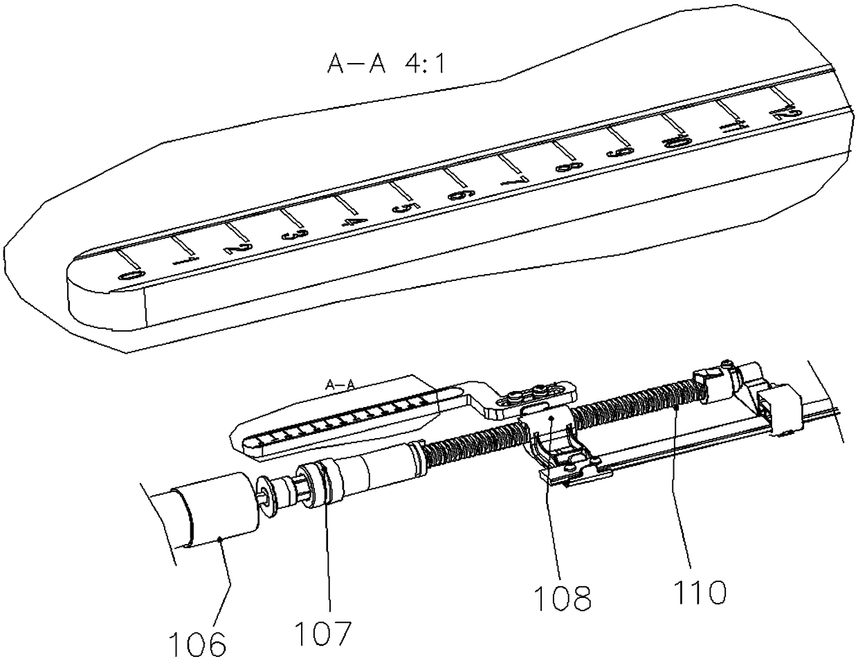
The invention discloses a tilt adjustment method for an electric tilt antenna and a corresponding device, and aims at solving the technical problem that in the prior art, tilt adjustment of the electric tilt antenna is not in place due to a structure fit clearance, and then communication signal coverage and user experience are influenced. The method comprises the following steps: whether or not atarget position of a phase shifter push-pull rod is in the positive direction of an initial position is determined, wherein the initial position is the position where the phase shifter push-pull rod stays on a stroke lever before tilt adjustment, the target position is the position where the phase shifter push-pull rod needs to stay on the stroke lever after tilt adjustment, and the positive direction is the direction pointing to the stroke lever destination point from the stroke lever start point; if yes, a motor is controlled to drive the phase shifter push-pull rod to move in the position direction to the target position and then move a structure clearance compensation distance in the negative direction; or the motor is controlled to drive the phase shifter push-pull rod to move in thepositive direction and cross the target position and then move in the negative direction to the target position; and otherwise, the motor is controlled to drive the phase shifter push-pull rod to movein the negative direction to the target position.

Description

technical field [0001] The invention relates to the technical field of mobile communication antennas, in particular to a method for adjusting the inclination angle of an electrically adjustable antenna and a corresponding device. Background technique [0002] In the field of mobile communication technology, the downtilt angle of the antenna is a very important technical parameter in the antenna work. The parameters such as the angle, strength and area of ​​the mobile signal coverage will change with the change of the downtilt angle of the antenna. Generally, in actual work, the downtilt angle of the antenna needs to be adjusted according to different situations. The downtilt angle of the electronically adjustable antenna is divided into mechanical downtilt angle and electrical downtilt angle. Among them, adjusting the mechanical downtilt angle is cumbersome and requires manual adjustment on the station, which is time-consuming and labor-intensive. However, adjusting the elec...

Claims


Application Information

Patent Timeline
Patent Type & Authority Applications(China)
IPC IPC(8): H01Q3/32
CPCH01Q3/32
Inventor 宋拟周浩马泽峰胡建华何海雁刘培涛
Owner COMBA TELECOM TECH (GUANGZHOU) CO LTD
Learn More