
Switch control circuit and switch control system

A switch control circuit and switch technology, which is applied in general control systems, control/regulation systems, circuits, etc., can solve the problem of low reliability of switch control circuits and achieve the effect of protecting contacts

Active Publication Date: 2022-05-17
WENZHOU MTLC ELECTRIC APPLIANCES
View PDF9 Cites 0 Cited by
  • Summary
  • Abstract
  • Description
  • Claims
  • Application Information

AI Technical Summary

Problems solved by technology

[0005] In view of this, an embodiment of the present invention provides a switch control circuit and a switch control system to solve the problem of low reliability of the existing switch control circuit

Method used


Image

  • Switch control circuit and switch control system
  • Switch control circuit and switch control system
  • Switch control circuit and switch control system

Examples


Embodiment Construction

[0049] In order to make the purpose, technical solutions and advantages of the embodiments of the present invention clearer, the technical solutions in the embodiments of the present invention will be clearly and completely described below in conjunction with the drawings in the embodiments of the present invention. Obviously, the described embodiments It is a part of embodiments of the present invention, but not all embodiments. Based on the embodiments of the present invention, all other embodiments obtained by those skilled in the art without making creative efforts belong to the protection scope of the present invention.

[0050]In the description of the present invention, it should be noted that the terms "first", "second", and "third" are used for description purposes only, and should not be understood as indicating or implying relative importance.

[0051] In addition, the technical features involved in the different embodiments of the present invention described below ...


PUM


Abstract

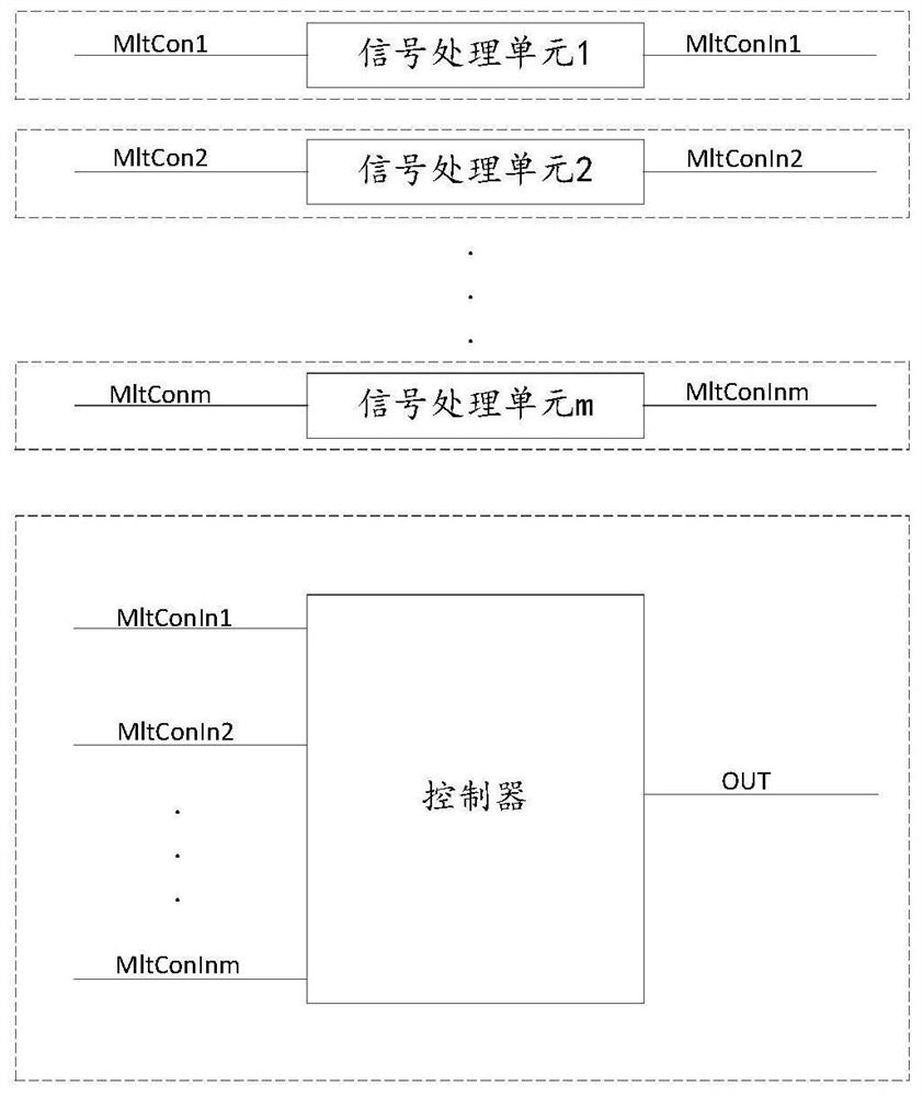
The present invention relates to the technical field of electronic circuits, and discloses a switch control circuit and a switch control system, wherein the control circuit includes: a plurality of parallel signal processing units, the signal processing unit has a first controllable switch; the first controllable The first end of the switch is connected to the first voltage signal, the second end is connected to the first port of the controller, and the third end is connected to the second voltage signal; the first voltage signal and the second voltage signal control the first control the on and off of the switch, and convert the first voltage signal into a third voltage signal; the third voltage signal is connected to the first port of the controller; the controller is configured to , and send the switch control command to the terminal to be controlled. After converting the high strong electric signal into a low stable weak electric signal, the circuit combines the controller to realize multi-channel switch control, and only processes the voltage signal in the whole circuit, avoiding the processing of various types of signals and ensuring the multi-channel Reliability of switch control.

Description

technical field [0001] The invention relates to the technical field of electronic circuits, in particular to a switch control circuit and a switch control system. Background technique [0002] The operation of the power switch of the electrical equipment is generally controlled locally by the user, and can only be operated at a fixed position, and can only be operated when the user needs to go to the side of the electrical equipment. [0003] With the improvement of people's living standards and quality, the types of electrical equipment on the market are increasing, and people's requirements for the intelligence of electrical equipment are getting higher and higher, and the intelligence of power switch control of electrical equipment is particularly important. The above-mentioned control method for electrical equipment requires the user to go to multiple electrical equipment in turn to manually control the power switch of each electrical equipment in some occasions where th...

Claims


Application Information

Patent Timeline
Patent Type & Authority Patents(China)
IPC IPC(8): G05B19/042
CPCG05B19/0423G05B2219/25257H03K17/13H01H9/56H01H47/32H01H47/005H03K17/133
Inventor 高伟
Owner WENZHOU MTLC ELECTRIC APPLIANCES
Learn More