Clamping mechanism for shoe sole friction test equipment and friction test equipment

A technology of clamping mechanism and testing equipment, which is applied to the measurement device of feet or shoe lasts, testing wear resistance, footwear, etc., which can solve the problems of inability to reflect the performance requirements of soles, high cost, and inability to perform friction tests. The effect is better, the structure is simple, and the shoe last is fixed and stable.

Pending Publication Date: 2019-03-08
361 DEGREES CHINA
View PDF12 Cites 2 Cited by
  • Summary
  • Abstract
  • Description
  • Claims
  • Application Information

AI Technical Summary

Problems solved by technology

However, during the actual movement of the shoes, due to the large difference in the weight of the wearer and the different forces on different positions of the same sole, the grip and wear resistance required by each part of the sole are also different, especially Sports shoes have a higher demand for grip and wear resistance. Taking basketball sports shoes as an example, due to the requirements for grip and wear resistance of the front sole and rear heel of the sole due to bouncing, emergency stop and other actions during basketball Therefore, it is necessary to perform friction tests on these important positions when performing friction tests before sole production; however, the existing test equipment is fixed for the test parts of the soles, which cannot reflect the actual routine use of the soles. performance requirements, it is impossible to simulate the friction test of the human body exerting force on important positions of the sole during actual exercise; in addition, the connection between the existing test equipment and the shoe last is fixed, and the shoe last on the test equipment is customized. If adjustments are made, the shoe last needs to be replaced again, and the existing shoe last cannot be used for testing, and a shoe last with a cost of up to 2,000 US dollars per piece needs to be customized; therefore, there is still room for further improvement of the existing shoe sole friction testing equipment

Method used


Image

  • Clamping mechanism for shoe sole friction test equipment and friction test equipment
  • Clamping mechanism for shoe sole friction test equipment and friction test equipment
  • Clamping mechanism for shoe sole friction test equipment and friction test equipment

Examples


Embodiment Construction

[0027] In order to make the technical problems, technical solutions and beneficial effects to be solved by the present invention clearer and more comprehensible, the present invention will be further described in detail below with reference to the accompanying drawings and embodiments. It should be understood that the specific embodiments described herein are only used to explain the present invention, but not to limit the present invention.

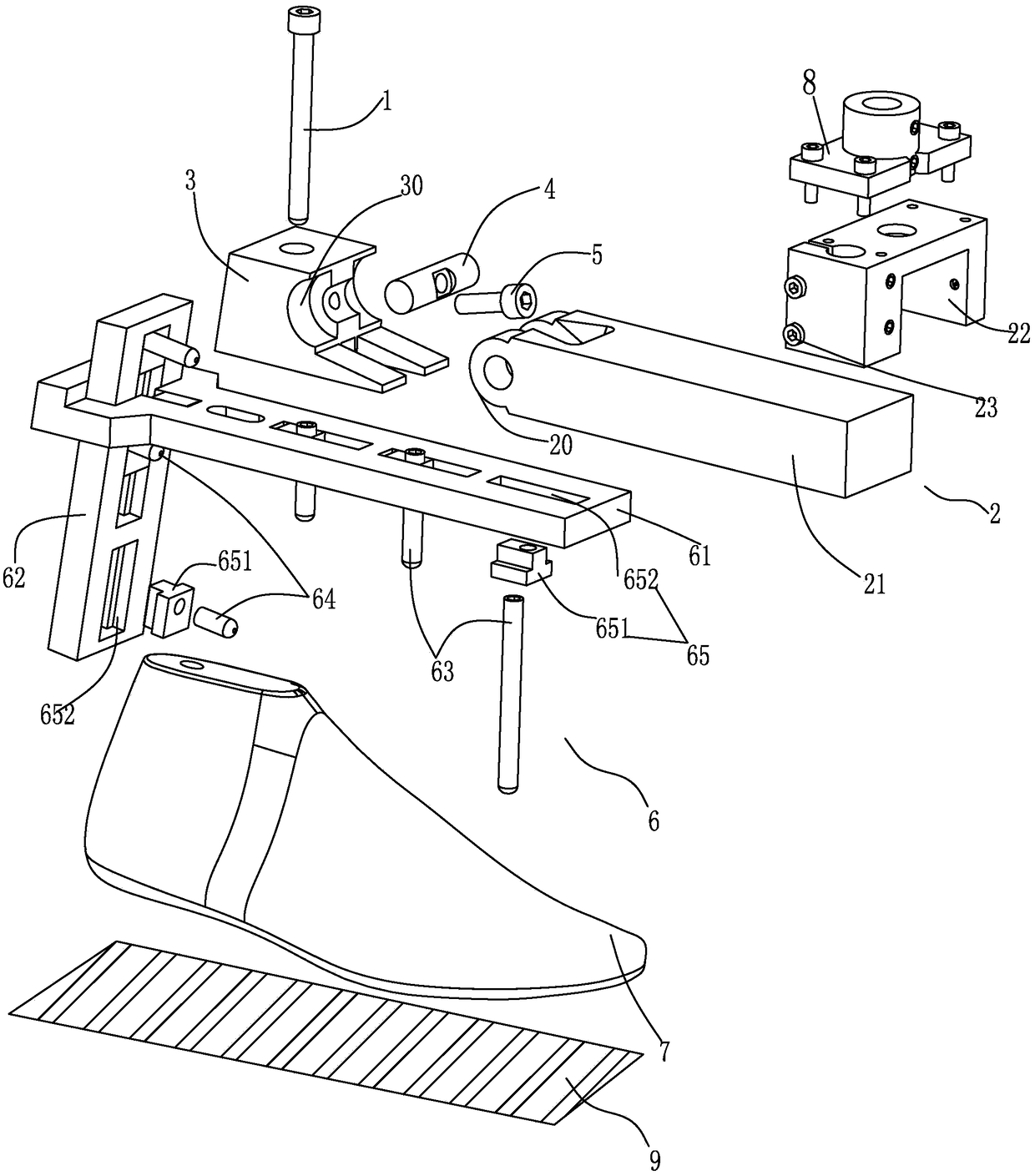
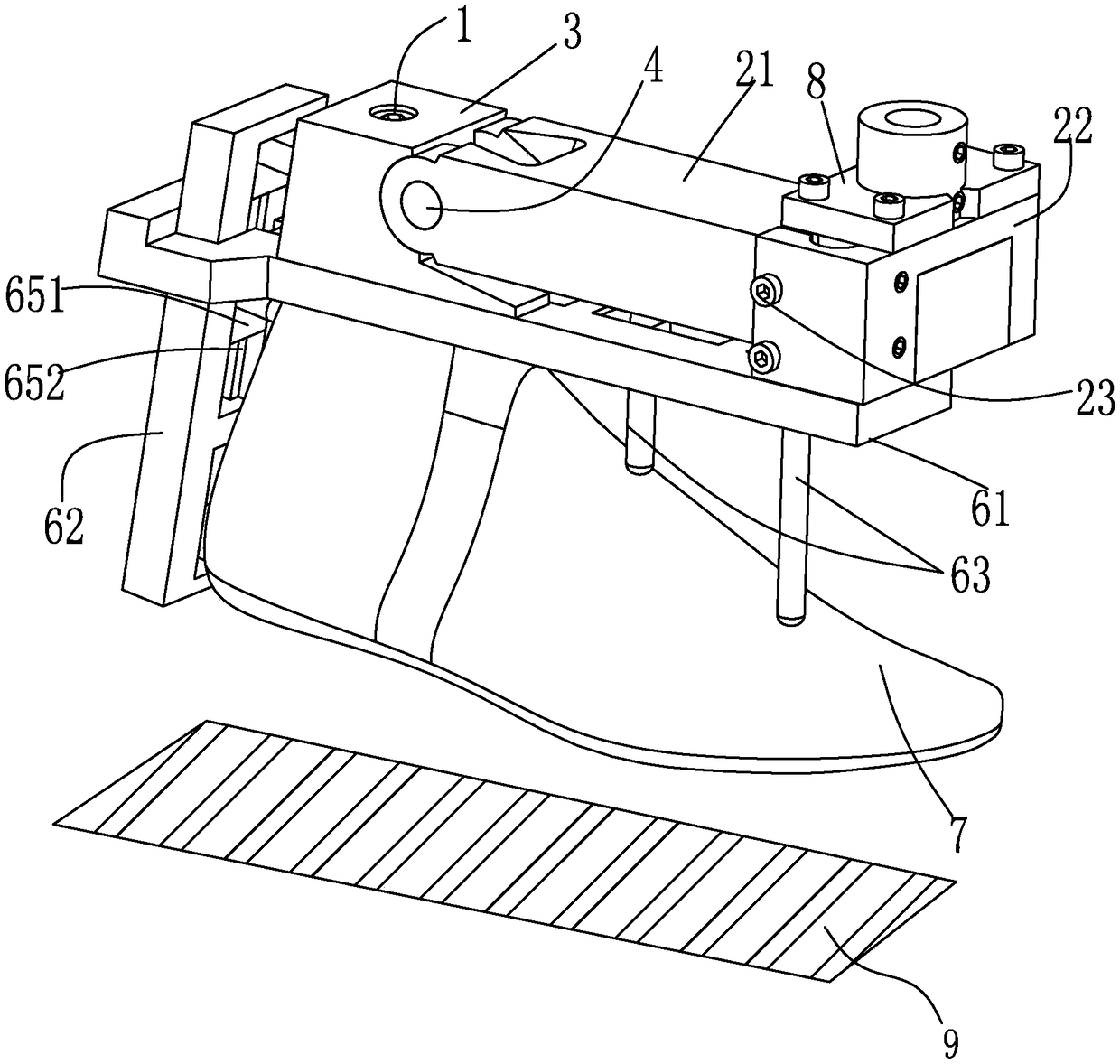
[0028] like figure 1 As shown, a clamping mechanism and friction testing equipment for sole friction testing equipment according to the present invention, the clamping mechanism is generally fixed on the fixed seat 8 of the sole friction testing equipment (not shown in the figure), and the sole The friction test equipment uses the tension meter to pull the fixed seat 8 with the rated tension set by the test to drive the clamping mechanism on the test platform 9 (can be set according to the use environment of different soles, such as: cem...


PUM


Abstract

The invention discloses a clamping mechanism for shoe sole friction test equipment and friction test equipment. The clamping mechanism comprises a connecting element, an assembling and connecting seat, a rotating seat, a hinging shaft and a tightening element, wherein the connecting element penetrates through the rotating seat and is used for fixing a shoe tree; the assembling and connecting seatand the rotating seat form hinging matching through the hinging shaft; the tightening element penetrates through the hinging shaft to be screwed with the rotating seat, and drives the assembling and connecting seat connected with the hinging shaft to tighten the rotating seat, so that the shoe tree connected with the rotating seat swings for a certain angle relative to the assembling and connecting seat. The clamping mechanism for shoe sole friction test equipment provided by the invention has the advantages that the structure is simple; the design is reasonable; the realization is easy; by regulating the inclination angle of the shoe tree, the friction test on different important positions of the shoe sole can be realized; the shoe product after the factory delivery can better meet the wearing requirements of users in the practical movement process.

Description

technical field [0001] The invention relates to the shoe-making industry, in particular to a clamping mechanism and a friction testing device for sole friction testing equipment. Background technique [0002] At present, shoes need to be tested for sole friction before production to test the grip and wear resistance of the produced shoes on different floors (such as cement pavement, tiled floor, wooden floor, smooth marble, ice surface, glass surface, etc.). Effect. However, in the actual exercise process of shoes, due to the large difference in the weight of the wearer and the different forces in different positions on the same sole, the grip and wear resistance required by each part of the sole are also different, especially Sports shoes have higher requirements for grip and wear resistance. Take basketball sports shoes as an example. During basketball, actions such as bouncing and emergency stop have requirements on the grip and wear resistance of the forefoot and rear h...

Claims


Application Information

Patent Timeline
Patent Type & Authority Applications(China)
IPC IPC(8): G01N3/56A43D1/08
CPCA43D1/08G01N3/56
Inventor 吴金攀魏书涛潘加浩
Owner 361 DEGREES CHINA
Why Eureka
Try Eureka