
A fully automatic machining equipment

A mechanical processing and fully automatic technology, which is applied in the direction of metal processing equipment, measuring/indicating equipment, drilling/drilling equipment, etc., can solve the problems such as the inability to automatically adjust the processing position, the cover is not tightly covered, and the drill bit is stuck. Achieve the effects of saving working time, convenient lighting, and buffering vibration

Active Publication Date: 2020-11-17
日照德信机械制造有限公司
View PDF5 Cites 0 Cited by
  • Summary
  • Abstract
  • Description
  • Claims
  • Application Information

AI Technical Summary

Problems solved by technology

[0006] The purpose of the present invention is to provide a fully automatic machining equipment, which has the advantage of automatically adjusting the processing position, and solves the problem that the existing fully automatic machining equipment cannot automatically adjust the processing position, and the processing of inclined surfaces is prone to cover cover Lax, resulting in splashing, easy to jam the drill bit technical problems

Method used


Image

  • A fully automatic machining equipment
  • A fully automatic machining equipment
  • A fully automatic machining equipment

Examples


no. 1 approach

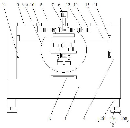
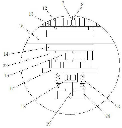
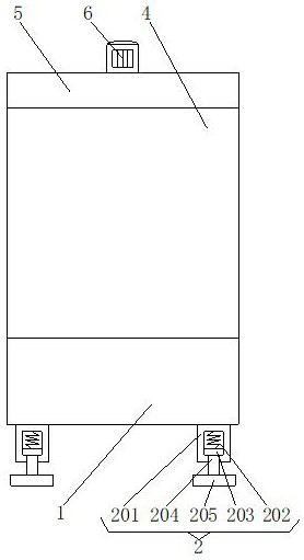
[0022] First implementation: see Figure 1-3 , a kind of fully automatic mechanical processing equipment, including an operation table 1, two support devices 2 are symmetrically arranged on the left and right sides of the bottom of the operation table 1, the support device 2 includes a connecting seat 201, and the top of the connecting seat 201 is connected to the bottom of the operation table 1 The bottom is fixedly connected, the top of the inner wall of the connecting seat 201 is fixedly connected with a buffer spring 202, the bottom of the buffer spring 202 is fixedly connected with a connecting slider 203 slidingly connected with the inner wall of the connecting seat 201, and the bottom of the connecting slider 203 is fixedly connected with a supporting leg 204 , the bottom of the support leg 204 runs through the connection seat 201 and extends to the outside of which a support seat 205 is fixedly connected. By setting the support device 2, it plays the role of buffering t...

no. 2 approach

[0025] The second embodiment: as shown in claim 1, a fully automatic mechanical processing equipment, including an operation platform 1, two support devices 2 are symmetrically arranged on the left and right sides of the bottom of the operation platform 1, and the operation platform The middle point of the top of 1 is fixedly connected with a fixed mold 3, and the left and right sides of the top of the operating table 1 are fixedly connected with support plates 4, and the tops of the two support plates 4 are fixedly connected by a top plate 5, and the top of the top plate 5 A drive motor 6 is fixedly connected to the midpoint, and a drive shaft 7 is fixedly connected to the output shaft of the drive motor 6. The bottom of the drive shaft 7 runs through the top plate 5 and extends below it to be fixedly connected with a drive gear 8. The bottom of the top plate 5 and the left and right sides of the drive shaft 7 are provided with a chute 9, the inner wall of the chute 9 is slida...


PUM


Abstract

The invention discloses full-automatic mechanical processing equipment. The full-automatic mechanical processing equipment comprises an operation platform. Two supporting devices are symmetrically arranged on the left and right sides of the bottom of the operation platform. A fixed die is fixedly connected at the middle point of the top of the operation platform. Supporting plates are correspondingly and fixedly connected to the left and right sides of the top of the operation platform. The tops of the two supporting plates are fixedly connected through a top plate. A driving motor is fixedlyconnected at the middle point of the top of the top plate. A driving rotating shaft is fixedly connected to an output shaft of the driving motor. The bottom of the driving rotating shaft penetrates through the top plate, extends to the lower part of the top plate and is fixedly connected with a driving gear. According to the full-automatic mechanical processing equipment, the operating platform, the supporting plates, the top plate, the driving motor, the driving rotating shaft, the driving gear, a supporting sliding block, a rack plate, a supporting sliding sleeve, a supporting sliding plate,air cylinders, a mounting plate, a drilling motor and a drilling bit are matched with each other, so that full-automatic drilling equipment can automatically adjust the processing position, the laborintensity of a user is reduced, and a large amount of working time is saved.

Description

technical field [0001] The invention relates to the technical field of mechanical processing equipment, in particular to a fully automatic mechanical processing equipment. Background technique [0002] Fully automatic refers to the comprehensive automation of mechanical devices and product production and processing operations. At present, with the high popularity of computer technology, industries such as industrial product manufacturing, parts processing, and human social life products have all entered the era of all-round automatic production controlled by computer programming. In addition, industries such as military industry, aerospace equipment, scientific research, agriculture, and electric power have all implemented full automation by computer-aided production. It can also be said that the interpretation of the word "automatic" is also a process in which industrial and agricultural production does not rely on manual labor but is automatically operated by machinery. ...

Claims


Application Information

Patent Timeline
Patent Type & Authority Patents(China)
IPC IPC(8): B23B39/16B23Q11/08B23Q17/24B23Q1/01
CPCB23B39/16B23Q1/015B23Q11/08B23Q17/2404
Inventor 王永
Owner 日照德信机械制造有限公司
Learn More