
Sampling device for clinical biopsy sample in oncology

A biopsy sample and sampling device technology, applied in the field of medical devices, can solve the problems of complex operation, sample damage, influence of sample purity, etc., and achieve the effect of reasonable structure design

Inactive Publication Date: 2019-03-08
宋超
View PDF1 Cites 8 Cited by
  • Summary
  • Abstract
  • Description
  • Claims
  • Application Information

AI Technical Summary

Problems solved by technology

Most of the traditional tumor sampling devices use syringes or slices to sample, which is not only complicated to operate, but also uses negative pressure to suck out the samples, which is easy to cause damage to the samples. For example, in the Chinese invention patent with the announcement number CN107898479A, an easy-to-operate The tumor cell sampling device moves the movable rod to the left by pressing the movable block, and uses the deformation of the airbag to drive the push rod to push the rubber block to clamp the movable rod so that the movable rod stops rotating. Turn reset, easy to operate
However, similar to most tumor cell sampling devices, the samples taken out by this invention after puncture include not only tumor cells, but also part of the epidermis and muscle tissue, which has a certain impact on the purity of the sample, so further improvement is needed

Method used


Image

  • Sampling device for clinical biopsy sample in oncology
  • Sampling device for clinical biopsy sample in oncology
  • Sampling device for clinical biopsy sample in oncology

Examples


Embodiment Construction

[0015] Attached below Figure 1~6 The present invention is described in detail below.

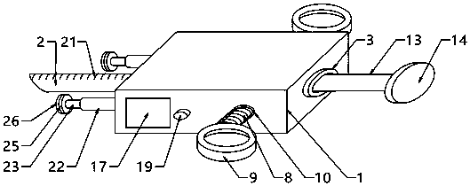
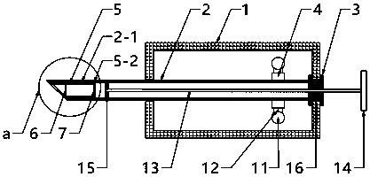
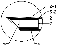
[0016] like Figure 1~6 As shown, the present invention includes an outer box 1, a puncture needle 2, a sampling tube 5 and a push rod 13. The puncture needle 2 is hollow and inserted into the outer box 1, and the right end passes through the right end surface of the outer box 1 and is fixedly connected with the outer box 1. The opening on the right side of the outer box 1 is a suitable I-shaped stop ring 3 to ensure that the puncture needle 2 can only rotate and cannot move left and right. The right side of the puncture needle 2 is fixedly sleeved with a gear 4 inside the outer box 1. The sampling tube 5 is formed by buckling two semi-circular sampling needles 5-1, the sampling tube 5 is inserted into the inner left end of the puncture needle 2, and the upper and lower ends of each sampling needle 5-1 are fixedly connected with sliders 5-2 at the right end, The left end of the inner wall...


PUM


Abstract

The invention relates to the technical field of medical instruments, in particular to a sampling device for a clinical biopsy sample in oncology. The device comprises an outer box, a puncture needle,a sampling tube and a push rod, wherein the puncture needle is inserted into the outer box; the sampling tube is formed by buckling two semi-annular sampling needles and is inserted into the inner left end of the puncture needle; a first cutting line and a second cutting line are fixedly connected to the left and right ends of one sampling needle respectively; L-shaped rods inside the outer box are fixedly connected to the two connecting rods on the outer box; racks meshing with gear wheels on the puncture needle are fixedly connected to the L-shaped rods; the push rod is inserted into the puncture needle; and a push block is fixedly connected to the left end of the push rod. The structural design is reasonable, skin and muscle tissues enter into the right side of the sampling tube in thepuncture needle by inserting the puncture needle into a tumor tissue, and the tumor tissue enters into the sampling tube; holding rings are pressed to rotate the sampling tube; the tumor tissue can becut by using the first cutting line and the second cutting line; and a pure tumor tissue sample can be obtained by pushing out the sampling tube by using the push rod.

Description

technical field [0001] The invention relates to the technical field of medical devices, in particular to a sampling device for clinical biopsy samples in the department of oncology. Background technique [0002] Tumor refers to the new organism formed by the proliferation of local tissue cells under the action of various tumorigenic factors, because this new organism is mostly in the form of space-occupying blocky protrusions, also known as neoplasm, regardless of its cell shape and tissue structure. In general, they are different from the normal tissue from which they originated. Tumors are divided into benign and malignant. Not all tumors are cancers. Only malignant tumors can be called cancers. Cells from the diseased site are sampled for analysis, thus requiring specialized tumor sampling devices. Most of the traditional tumor sampling devices use syringes or slices to sample, which is not only complicated to operate, but also uses negative pressure to suck out the samp...

Claims


Application Information

Patent Timeline
IPC IPC(8): A61B10/02
CPCA61B10/0266
Inventor 宋超
Owner 宋超
Learn More