Display screen and display device
A technology of display screen and rotary drive device, which is applied in the direction of optics, instruments, electrical components, etc., can solve the problems of high position setting requirements, inconvenient viewers, and no mutual interference, etc., to solve the high position setting requirements and improve The effect of pixel spatial distribution, position and light direction is easy
- Summary
- Abstract
- Description
- Claims
- Application Information
AI Technical Summary
Problems solved by technology
Method used
Image
Examples
Embodiment 1
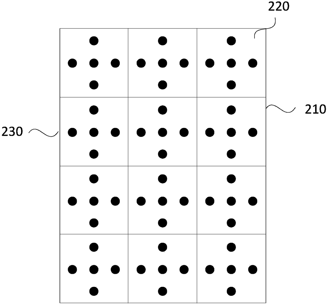
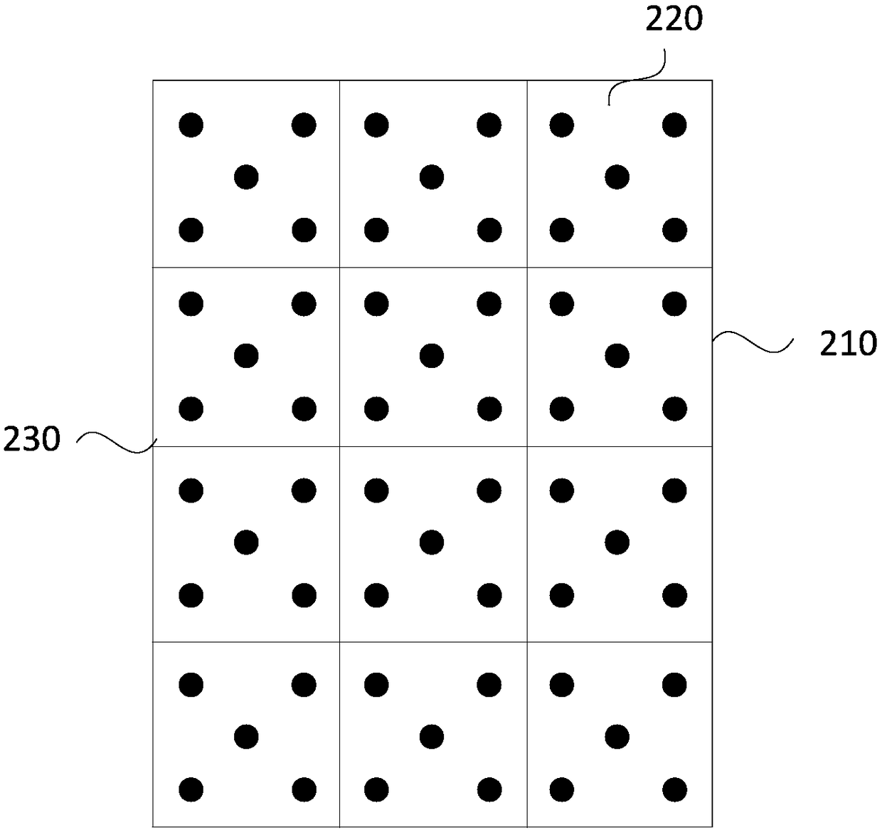
[0025] Figure 2a A structural top view of a display screen provided in Embodiment 1 of the present invention, Figure 2b A structural top view of a display screen provided in Embodiment 1 of the present invention, Figure 2c It is a front view of the structure of a display screen provided by Embodiment 1 of the present invention, Figure 2d A structural front view of a display screen provided in Embodiment 1 of the present invention, wherein the display screen 210 includes a plurality of pixels 220 arranged in an array.
[0026] Each pixel is provided with at least two luminous sources, the luminous sources are fixed on the fixed plate, and are separated by a set distance in the direction perpendicular to the plane of the display screen, and each luminous source is used for the light emitted by the luminous source Image data representing pixels.
[0027] The rotation driving device is used to drive the rotation angle of the light emitting source to adjust the direction of ...
Embodiment 2
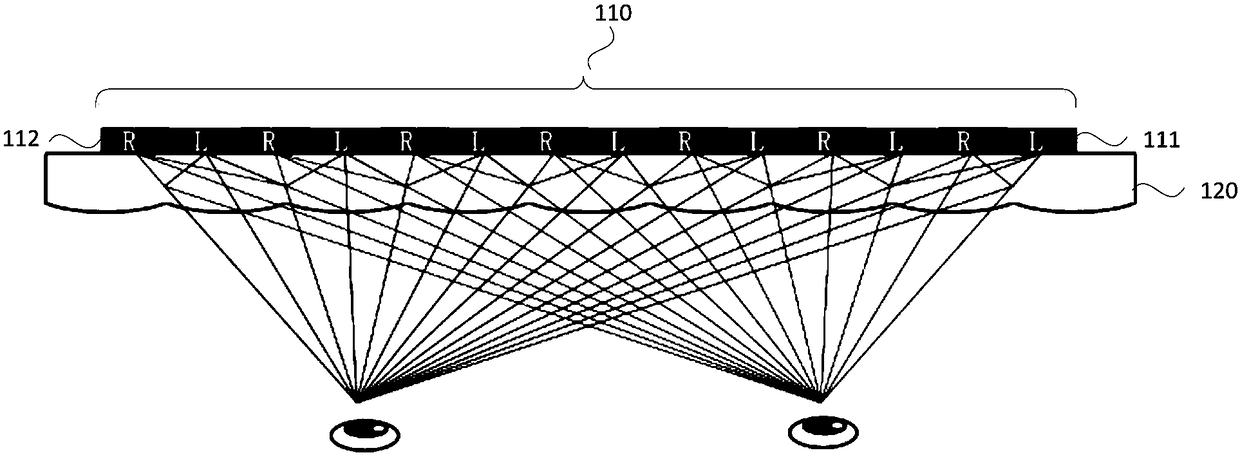
[0051] Figure 3a It is a schematic diagram of the positional relationship between two types of light sources and eyes in a display screen provided by Embodiment 2 of the present invention. This embodiment optimizes Embodiment 1. Specifically, this embodiment further describes the pixel points corresponding to The classification and position orientation of light sources, etc.
[0052] Each of the light-emitting sources is divided into a left-eye light-emitting source and a right-eye light-emitting source;
[0053] The light source for the left eye is set to emit light toward the left eye outside the display screen;
[0054] The light source for the right eye is arranged to emit light toward the position of the right eye outside the display screen.
[0055] In this embodiment, each of the light sources can be divided into at least a left-eye light source 310 and a right-eye light source 320; the left-eye light source 310 is set to emit light toward the left eye position 340 o...
Embodiment 3
[0073] On the basis of the above embodiments, the display screen may further include: a human eye position identification module, located in the display screen, used to identify the human eye position of the viewer in front of the display screen and the distance between the display screen and the human eye position. distance. In this embodiment, the human eye recognition module can be obtained through image recognition by a camera in front of the screen. The camera captures the image of the face in front of the screen through a lens and projects it onto the surface of the image sensor, and judges the position of the human eye in the image through image recognition technology. The specific position, and then determine the position of the human eyes of the viewer in front of the display screen and the distance from the display screen according to various parameters such as the size and shape of the image, and send the image of the eyes and related data to the eye distance recogni...
PUM
| Property | Measurement | Unit |
|---|---|---|
| Straight line distance | aaaaa | aaaaa |
Abstract
Description
Claims
Application Information
 - R&D
- Intellectual Property
- Life Sciences
- Materials
- Tech Scout
- Unparalleled Data Quality
- Higher Quality Content
- 60% Fewer Hallucinations
Browse by: Latest US Patents, China's latest patents, Technical Efficacy Thesaurus, Application Domain, Technology Topic, Popular Technical Reports.
© 2025 PatSnap. All rights reserved.Legal|Privacy policy|Modern Slavery Act Transparency Statement|Sitemap|About US| Contact US: help@patsnap.com


