Variable speed iron core vibrating motor

An iron core vibration and variable technology, which is applied in the direction of electric components, sliding contact resistors, electrical components, etc., can solve the problems of unreachable, large speed deviation, large vibration sense deviation, etc., to reduce speed deviation and vibration sense deviation , the effect of improving performance

Inactive Publication Date: 2019-03-05
ZHEJIANG DONGYANG CHENGJI ELECTRO MECHANICS CO LTD
View PDF5 Cites 0 Cited by
  • Summary
  • Abstract
  • Description
  • Claims
  • Application Information

AI Technical Summary

Problems solved by technology

) in the industry can only achieve about 1.0, and cannot reach above 1.33
Therefore, the existing iron core vibration motor has the defects of large speed deviation and non-adjustable speed
The speed determines the vibration feeling, and a large speed deviation means a large vibration feeling deviation, which directly affects the user experience

Method used


Image

  • Variable speed iron core vibrating motor
  • Variable speed iron core vibrating motor
  • Variable speed iron core vibrating motor

Examples


Embodiment

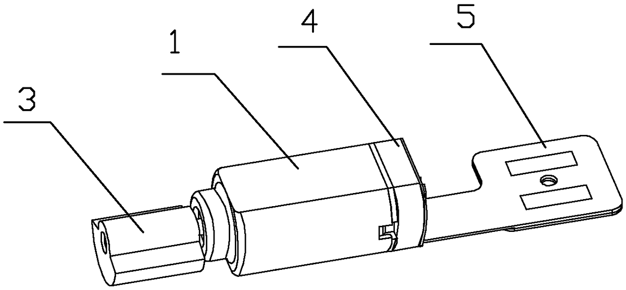
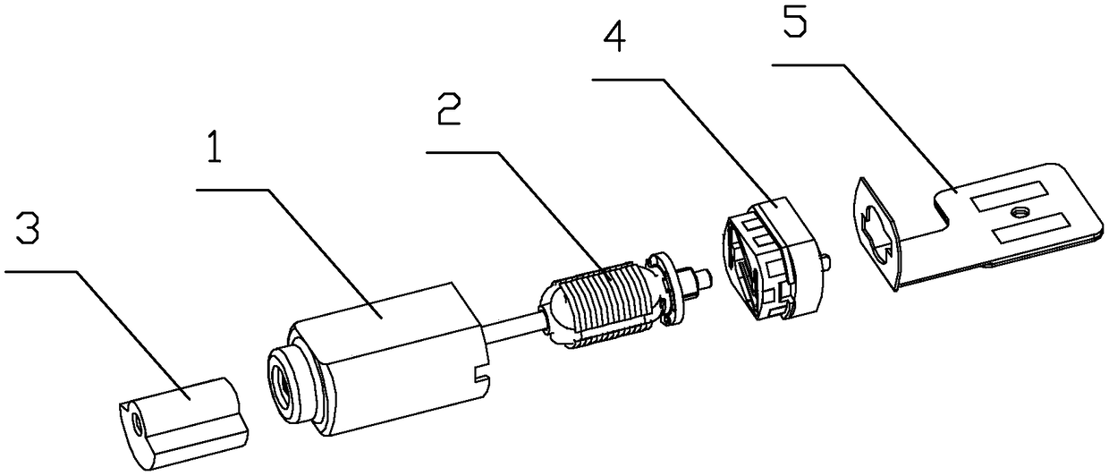
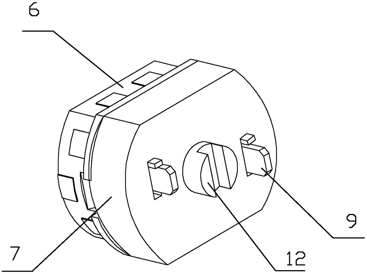
[0019] Embodiment: a kind of variable speed iron core vibration motor of the present embodiment, such as figure 1 , figure 2 As shown, it includes a casing 1, a rotor assembly 2 installed in the casing, a vibrator 3 installed at both ends of the casing, and an end cover assembly 4. A circuit board 5 is installed on the side of the end cover assembly away from the casing. The end cover assembly includes a base 6, a rear cover 7 and an adjustable resistor 8, the base is connected to the casing, the rear cover is covered on the rear side of the base, and the rear cover is connected to the circuit board. Two brushes 9 and a bearing 10 are pressed into the base, the bearing is located at the center of the base, the two brushes are arranged symmetrically around the center of the base, and the bearings and the brushes are respectively connected with the rotor assembly. Both the base and the back cover have two brush installation holes, and the pins of the brushes are inserted into ...


PUM


Abstract

The invention relates to a variable speed iron core vibrating motor, comprising a machine shell, a rotor assembly set in the machine shell, and a vibrator and an end cover assembly which are set at two ends of the machine shell. The end cover assembly comprises a base, a rear cover and an adjustable resistor. Two electric brushes are mounted on the base. The rear cover covers the rear side of thebase. The base is connected with the machine shell. The rear cover is connected with a circuit board. The adjustable resistor is set in space enclosed by the rear cover and the base. The adjustable resistor comprises a resistor body, a knob, a movable elastic sheet and a fixed elastic sheet. After the knob is mounted on the rear cover, the movable elastic sheet and the fixed elastic sheet are sleeved on the knob. One end of the resistor body and the fixed elastic sheet is connected with the two electric brushes. The movable elastic sheet is in contact connection with the resistor body. According to the variable speed iron core vibrating motor, the adjustable resistor is set in the end cover assembly, through adjustment of the adjustable resistor, a current value flowing through a rotor coil is adjusted and finally rotation speed of the motor is adjusted, so rotation speed deviation and vibrating sense deviation are reduced, and performance of the iron core vibrating motor is improved.

Description

technical field [0001] The invention relates to an iron core vibration motor, in particular to a variable speed iron core vibration motor. Background technique [0002] The existing iron core vibration motor includes a casing, a rotor assembly inside the casing, a vibrator and an end cover assembly respectively located at both ends of the casing, and the end cover assembly is pressed into the plastic end cover by 2 pieces of brushes and 1 bearing. Composition, the brush faces the casing, and the circuit board is connected to the end cover assembly. [0003] Due to the difference in materials and processing accuracy, the current speed specification of the iron core vibration motor is usually 14000±2500rpm, and the deviation is close to 35% of the center value of the specification, so the speed CPK value (CPK value is an indicator used to represent the process capability. Process capability It is the ratio of the allowable maximum variation range of process performance to the...

Claims


Application Information

Patent Timeline
Patent Type & Authority Applications(China)
IPC IPC(8): H02K11/00H01C10/32
CPCH01C10/32H02K11/0094
Inventor 周拾金
Owner ZHEJIANG DONGYANG CHENGJI ELECTRO MECHANICS CO LTD
Why Eureka
Try Eureka