refrigerator
A technology for refrigerators and storage rooms, applied in the field of refrigerators, can solve the problems of increased manufacturing costs and complex air passage structures, and achieve the effect of simplifying the air passage structure
- Summary
- Abstract
- Description
- Claims
- Application Information
AI Technical Summary
Problems solved by technology
Method used
Image
Examples
Embodiment approach 1
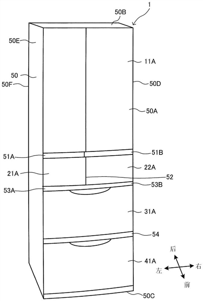
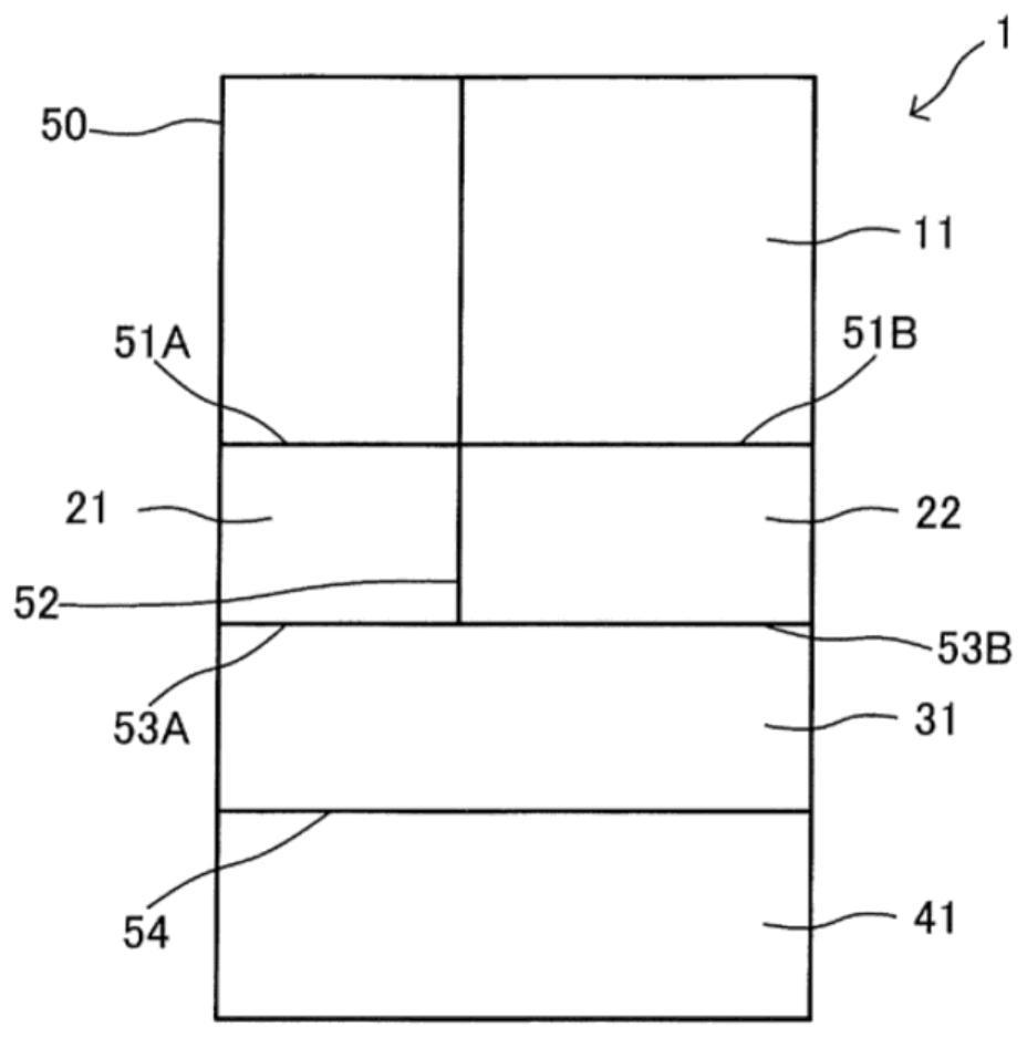
[0035] figure 1 It is an external perspective view schematically showing an example of refrigerator 1 according to Embodiment 1 of the present invention. figure 2 It is a schematic front view schematically showing the layout of the storage room of the refrigerator 1 . based on figure 1 with figure 2 The configuration of the refrigerator 1 will be described. In addition, in the following description, refrigerator compartment 11, ice making compartment 21, temperature switching compartment 22, vegetable compartment 31, and freezer compartment 41 may be collectively referred to as storage compartments.
[0036] Such as figure 2 As shown, the refrigerator 1 is arranged in the order of a refrigerating chamber 11 , an ice making chamber 21 , a temperature switching chamber 22 , a vegetable chamber 31 , and a freezing chamber 41 from above. The ice making chamber 21 and the temperature switching chamber 22 are arranged adjacently, the ice making chamber 21 is located on the lef...
Embodiment approach 2
[0148] Figure 8 It is an enlarged and schematic cross-sectional view of a part of refrigerator 1A according to Embodiment 2 of the present invention. based on Figure 8 1A of refrigerators in Embodiment 2 of this invention are demonstrated. Figure 8 is the same as that shown in Embodiment 1 Image 6 corresponding figure. exist Figure 8 Arrows indicate air flow.
[0149] In addition, in Embodiment 2, the difference from Embodiment 1 will be mainly described, and the same reference numerals will be attached to the same parts as Embodiment 1, and description will be omitted.
[0150] In Embodiment 2, the configuration of the fifth blowing air passage 411 is different from that of the fifth blowing air passage 411 described in Embodiment 1. As shown in FIG. In order to distinguish it from the fifth blowing air path 411 of Embodiment 1, in Embodiment 2, it demonstrates as 5th blowing air path 411C. The other configurations of the second embodiment are as described in the ...
Embodiment approach 3
[0163] Figure 9 It is a schematic diagram for demonstrating the air circulation path 80 of the refrigerator 1B which concerns on Embodiment 3 of this invention. Figure 10 is short for Figure 9 Cutaway view of the Y-Y section. Figure 11 It is an explanatory drawing which schematically shows the flow of the air of refrigerator 1B. based on Figure 9 ~ Figure 11 The refrigerator 1B is described. In addition, in Figure 9 ~ Figure 11 Arrows indicate air flow. Also in Figure 9 In the figure, the case where a chiller compartment is installed in the refrigerator compartment 11 is shown as an example.
[0164] In addition, in Embodiment 3, differences from Embodiment 1 and Embodiment 2 will be mainly described, and the same parts as Embodiment 1 and Embodiment 2 will be assigned the same reference numerals and descriptions will be omitted.
[0165] The lower end of cooler 600 disposed in cooler chamber 27 is located below bottom plate surface 31B of vegetable compartment ...
PUM
 Abstract
Description
Claims
Application Information
 - R&D Engineer
- R&D Manager
- IP Professional
- Industry Leading Data Capabilities
- Powerful AI technology
- Patent DNA Extraction
Browse by: Latest US Patents, China's latest patents, Technical Efficacy Thesaurus, Application Domain, Technology Topic, Popular Technical Reports.
© 2024 PatSnap. All rights reserved.Legal|Privacy policy|Modern Slavery Act Transparency Statement|Sitemap|About US| Contact US: help@patsnap.com


