Infectious disease negative pressure isolation ward

A negative pressure isolation and infectious disease technology, applied in the field of isolation wards, can solve the problems of no setting, deepening, poor sound insulation effect of negative pressure isolation wards, etc., and achieve the effect of safe and convenient use, scientific and reasonable structure

Inactive Publication Date: 2019-03-05
梁慧薇
View PDF0 Cites 13 Cited by
  • Summary
  • Abstract
  • Description
  • Claims
  • Application Information

AI Technical Summary

Problems solved by technology

[0003] The present invention provides a negative pressure isolation ward for infectious diseases, which can effectively solve the problem that the negative pressure isolation wards currently used in hospitals are not equipped with sound insulation boards, so that the sound insulation effect of the negative pressure isolation wards is not good, which affects patients. Rest and prolong the recovery time of the patient; there is no humidity sensor in the negative pressure isolation ward, and the patient needs to strictly control the humidity value in the ward during treatment. Respiratory tract infection is the mode of infection. If the patient’s respiratory tract is uncomfortable, the condition will be aggravated; there is no ultraviolet disinfection component, and it is impossible to ensure that the ward is in a relatively sterile environment at all times, and the infectious disease bacteria discharged from the patient’s respiratory tract cannot be killed in time. Threatening the health of medical staff and other issues

Method used


Image

  • Infectious disease negative pressure isolation ward
  • Infectious disease negative pressure isolation ward
  • Infectious disease negative pressure isolation ward

Examples


Embodiment

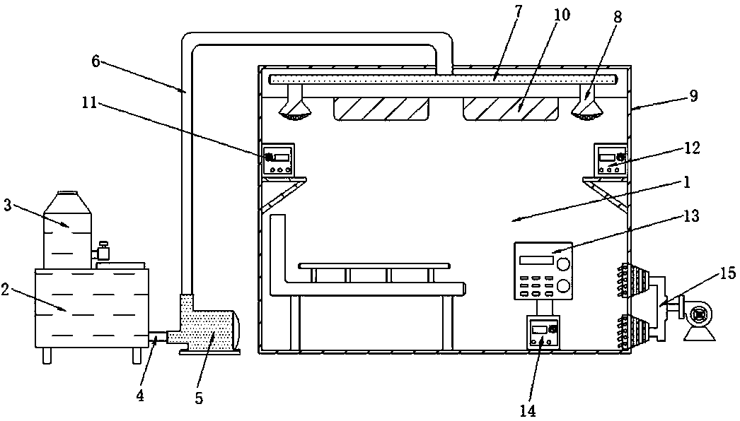
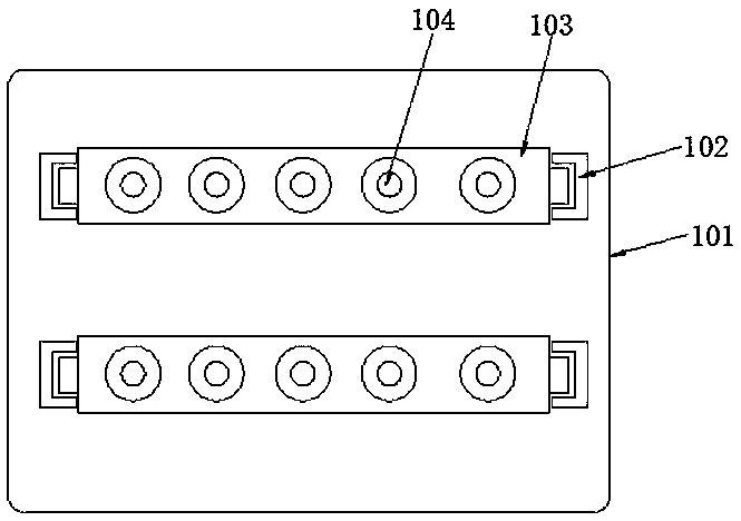
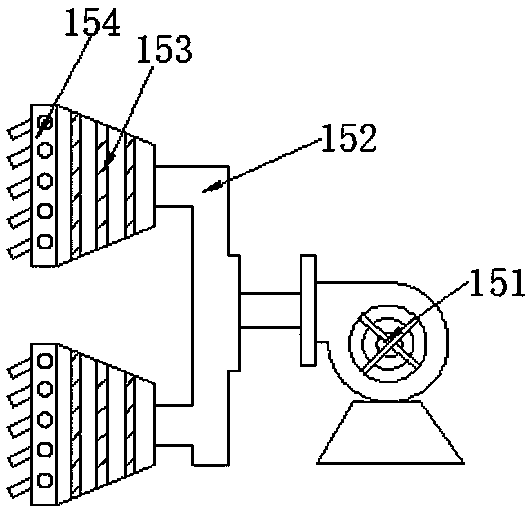
[0017] Example: such as Figure 1-3 As shown, the present invention provides a technical solution, a negative pressure isolation ward for infectious diseases, including a negative pressure ward body 1, a water storage tank 2, a dosing barrel 3, a water outlet pipe 4, a water pump 5, a first water delivery pipe 6, a second Two water pipes 7, atomizing nozzles 8, sound insulation boards 9, ultraviolet disinfection components 10, pressure sensors 11, humidity sensors 12, control panels 13, S7-200PLC controllers 14 and pressure regulating components 15, the left side of the negative pressure ward body 1 A water storage tank 2 is placed outside, and a dosing barrel 3 is installed on the outer side of the upper end of the water storage tank 2, and one end of the water outlet pipe 4 is connected to the outer side of one end of the water storage tank 2, and the other end of the water outlet pipe 4 is connected to a water pump 5, and the outer side of the upper end of the water pump 5 i...


PUM


Abstract

The invention discloses an infectious disease negative pressure isolation ward. The ward comprises a negative pressure ward body, a sound insulation plate, an ultraviolet disinfection assembly, a pressure sensor, a humidity sensor and a pressure adjusting assembly, the sound insulation plate is installed on the edge of the outer side of the negative pressure ward body, and the ultraviolet disinfection assembly is installed on the inner side of the top of the negative pressure ward body; the pressure sensor is installed on one side in the negative pressure ward body, the humidity sensor is installed on the other side in the negative pressure ward body, and the pressure adjusting assembly is installed on one side of the bottom of the negative pressure ward body. The ward is scientific and reasonable in structure and safe and convenient to use, by arranging the sound insulation plate, it is avoided that due to the poor sound insulation effect of the negative pressure isolation ward, the rest of the patient is influenced; the humidity sensor is arranged in the negative pressure isolation ward, the humidity value in the negative pressure isolation ward can be monitored frequently, and it is avoided that due to the fact that the humidity value is not in a correct range, the respiratory tract of the patient is discomfortable, and the disease deteriorates.

Description

technical field [0001] The invention relates to the field of isolation wards, in particular to a negative pressure isolation ward for infectious diseases. Background technique [0002] Negative pressure ward means that under special equipment, the air pressure inside the ward is lower than the air pressure outside the ward. In this case, in terms of air circulation, only fresh air from the outside can flow into the ward. The polluted air will not leak out, but will be discharged to a fixed place in time through a special channel. In this way, the place outside the ward will not be polluted, thereby reducing the chance of medical staff being infected in large numbers. This kind of ward is most suitable for rescuing patients with respiratory infectious diseases like SARS. The negative pressure isolation ward currently used in hospitals has no The sound insulation board is set up, so that the sound insulation effect of the negative pressure isolation ward is not good, which af...

Claims


Application Information

Patent Timeline
IPC IPC(8): E04H3/08G05D27/02A61G10/02
CPCE04H3/08A61G10/023G05D27/02
Inventor 梁慧薇
Owner 梁慧薇
Why Eureka
Try Eureka