Anti-vibration optical module and anti-vibration method

A technology of optical components and lens components, which is applied in the direction of optical components, optics, and light guides, can solve the problems of shortening the distance between the light emitting device and the photodetection device, reducing the distance between the light emitting device and the filtering device, and the substrate is susceptible to external interference, etc., to achieve Improve practicability, improve firmness, and reasonable structure

Pending Publication Date: 2019-03-01
大连仟面影视发展有限公司
View PDF8 Cites 1 Cited by
  • Summary
  • Abstract
  • Description
  • Claims
  • Application Information

AI Technical Summary

Problems solved by technology

[0003] The utility model patent of application publication number CN 203786343 U discloses an optical component. By opening a first groove on the substrate and detachably connecting the filter device to the bottom of the first groove, the distance between the light emitting device and the filter device is reduced. distance, thereby shortening the transmission path of light, shortening the distance between the light-emitting device and the photoelectric detection device, and rationally utilizing the overall layout space, the size of the light-emitting device can be made smaller, the manufacturing cost is saved, and the light path is avoided in the structure. The existence of the adhesive greatly improves the reliability and stability of the optical components, but in actual operation, although the device improves the stability of the optical components by avoiding the adhesive, the overall structure of the device is compact and shock-resistant The effect is poor, and the substrate is susceptible to external interference, which affects the efficiency of equipment operation

Method used


Image

  • Anti-vibration optical module and anti-vibration method
  • Anti-vibration optical module and anti-vibration method
  • Anti-vibration optical module and anti-vibration method

Examples


Embodiment 1

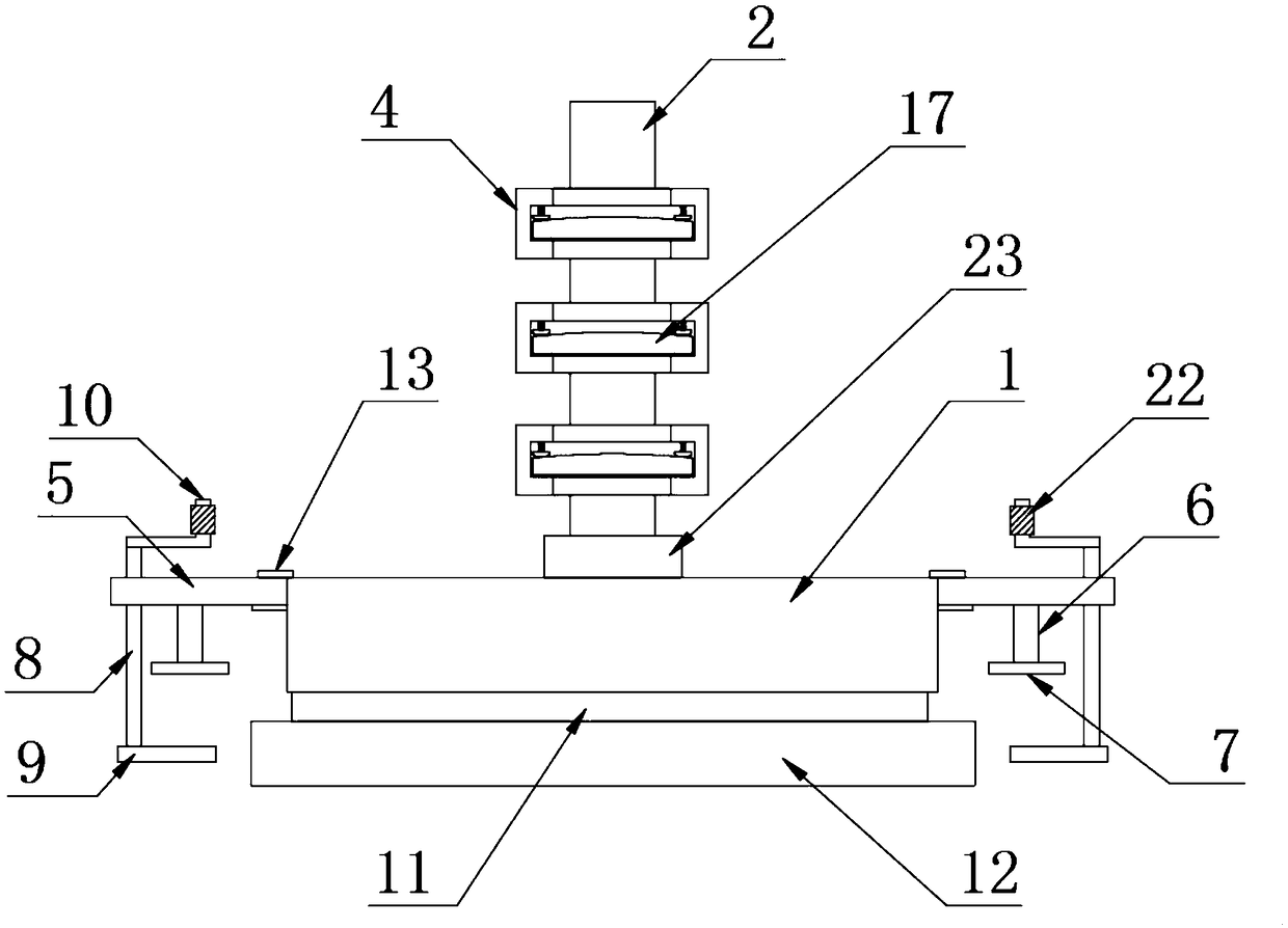
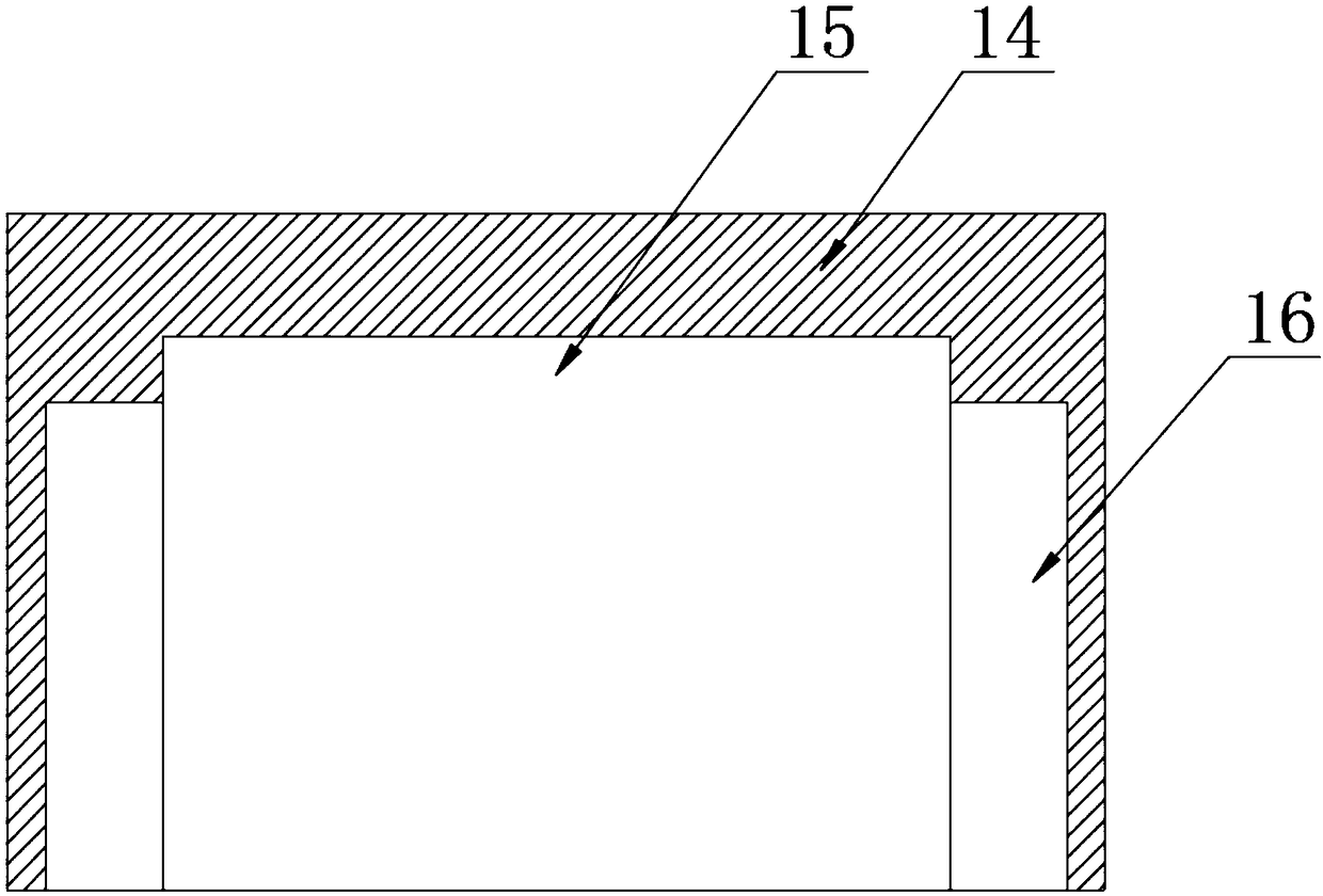
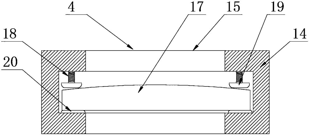
[0028] The present invention provides such Figure 1-4 The anti-shock optical assembly shown includes a base 1, a fixed rod 2 is arranged on the top of the base 1, and a plurality of fixed rings 3 are sleeved on the outside of the fixed rod 2, and a lens assembly 4 is arranged on one side of the fixed ring 3 Both sides of the base 1 are movably connected with adjustment rods 5 through hinges, the bottom of the middle part of the adjustment rod 5 is provided with a first support rod 6, and the bottom of the first support rod 6 is provided with a first splint 7. One end of the adjusting rod 5 away from the base 1 is provided with a moving rod 8, the bottom of the moving rod 8 is provided with a second splint 9, the top of the moving rod 8 is provided with a rotating rod 10, and the bottom of the base 1 is provided with a buffer pad 11, The bottom of the buffer pad 11 is provided with a base plate 12 , and the top and bottom of the connection between the base 1 and the adjusting ...

Embodiment 2

[0038] An anti-shock method for an anti-shock optical component, including the anti-shock optical component, also includes the following steps:

[0039] S1: Turn the adjustment lever 5;

[0040] S2: finally turn the rotating rod 10 to make the moving rod 8 move up and down at one end of the adjusting rod 5, so that the second splint 9 moves up and down;

[0041] S3: the top and the bottom of the connection between the base 1 and the adjusting rod 5 are provided with reinforcing plates 13, and the adjusting rod 5 can be flexibly connected to the base 1 through a hinge;

[0042] S4: the adjustment rod 5 is rotated left and right to expand the range in which the first splint 7 and the second splint 9 cooperate with each other;

[0043] S5: the buffer pad 11 is set, and a buffer zone is set between the base 1 and the substrate 12;

[0044] S3: Through the first splint 7 and the second splint 9 that cooperate with each other, the first splint 7 and the second splint 9 clamp the d...


PUM


Abstract

The invention discloses an anti-vibration optical module and an anti-vibration method. The optical module comprises a pedestal, and the top of the pedestal is provided with a fixed rod. An outer sideof the fixed rod is sleeved by a plurality of fixing rings, wherein one side of the fixing rings is provided with a lens assembly. Two sides of the pedestal are movably connected with an adjustment rods through hinges, and the central and bottom parts of the adjustment rods are provided with first support rods. The bottoms of the first support rods are provided with a first clamping board, and oneend, far from the pedestal, of the adjustment rods is provided with a moving rod. The bottom of the moving rod is provided with a second clamping board. The optical module is provided with a rotatingrod, and the rotating rod rotates to enable the moving rod to move up and down at one end of the adjustment rods, thereby enabling the second clamping board to move up and down. The first and secondclamping boards cooperate with each other, so that the device body is fixed on a table. Moreover, the device is fixed at two sides, thereby greatly improving the anti-vibration performance of the device. The setting of a reinforcing plate facilitates the improvement of the firmness between the pedestal and the adjustment rods.

Description

technical field [0001] The invention relates to the technical field of optical transceiver modules, in particular to an anti-shock optical component and an anti-shock method. Background technique [0002] Optics is an important branch of physics. It is also a discipline related to optical engineering technology. In a narrow sense, optics is the science of light and vision, and the word optics was only used for things related to eyes and vision in the early days. Optics, which is often said today, is in a broad sense, and it is a science that studies the generation, propagation, reception and display of electromagnetic radiation in a wide range of wavelengths from microwaves, infrared rays, visible light, ultraviolet rays to X-rays and gamma rays, as well as the interaction with matter. , focusing on the range of research from infrared to ultraviolet bands. It is an important part of physics. [0003] The utility model patent of application publication number CN 203786343...

Claims


Application Information

Patent Timeline
Patent Type & Authority Applications(China)
IPC IPC(8): G02B6/42G02B6/36
CPCG02B6/3616G02B6/4201G02B6/4256
Inventor 张权
Owner 大连仟面影视发展有限公司
Why Eureka
Try Eureka