Test method for wear resistance of electric detonator leg wire
A technology of wear resistance and testing method, which is applied in the direction of testing wear resistance, etc., can solve the problems of only one leg line can be tested at a time, which affects the safety level of detonators, etc., and achieves compact structure design, small footprint, and low failure rate Effect
- Summary
- Abstract
- Description
- Claims
- Application Information
AI Technical Summary
Problems solved by technology
Method used
Image
Examples
Embodiment 1
[0022] A method for testing the wear resistance of the detonator leg wire. On the wear resistance test device of the detonator leg wire, a certain action load is applied to the measured electric detonator leg wire, and it moves at a certain speed on the wear surface. , to simulate the wear force of the leg of the electric detonator under test, measure the time it takes for the insulating layer to be worn through, and evaluate the wear resistance of the leg through the time of wear.
Embodiment 2
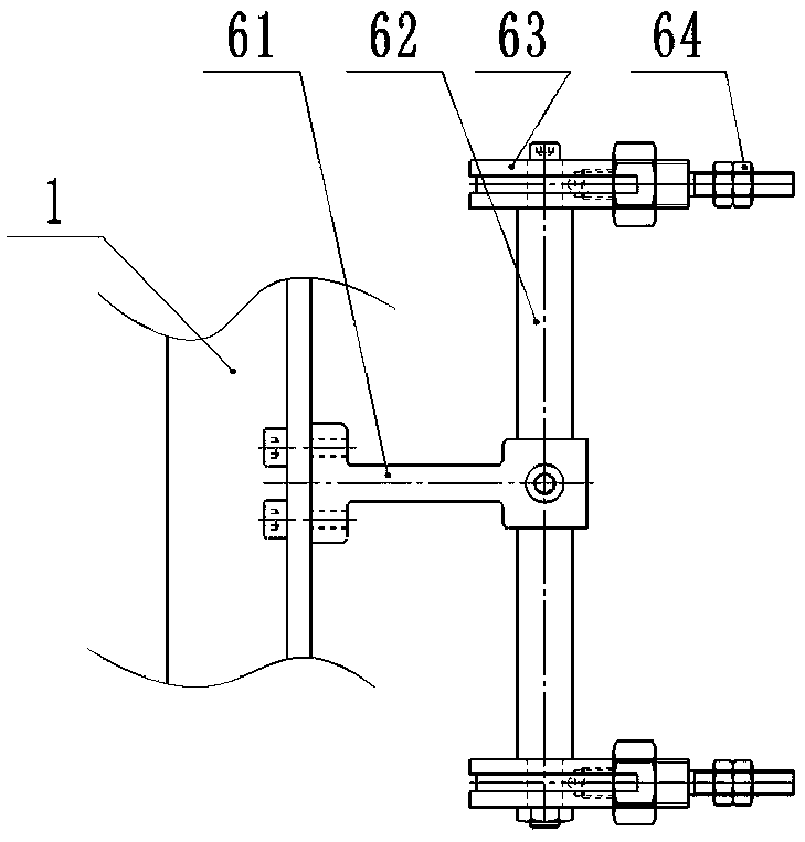
[0024] As a kind of test equipment of implementation example 1, such as figure 1 As shown, the detonator foot line wear resistance testing device includes a frame 1, a tension measuring mechanism 2 installed on the frame, a crimping mechanism 3, a rotating mechanism 4, a wire mechanism 5, and a tension adjusting mechanism 6; One end of the pin line is fixed on the tension measuring mechanism 2, the other end passes through the wire mechanism 5 and is fixed by the tension adjusting mechanism 6, and the test part of the detonator leg line to be tested is placed horizontally between the crimping mechanism 3 and the rotating mechanism 4 on the starting position.
[0025] The device for testing the wear resistance of the detonator leg line also includes a PLC control system, and the PLC control system controls components to start and stop in a logical order.
Embodiment 3
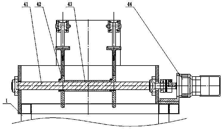
[0027] Such as figure 1 , figure 2 , image 3 As shown, as an optimization to Embodiment 2, the tension measuring mechanism 2 includes a gravity sensor 21, a leg fixing nut 22, the gravity sensor 21 is installed on the frame 1, and the leg fixing nut 22 is installed on the gravity sensor 21, It is used to connect one end of the leg wire of the electric detonator to be tested.
[0028] Described crimping mechanism 3 comprises pivot bar seat 31, pivot bar 32, counterweight bar 33, counterweight weight 34; Connect the counterweight bar 33, and the counterweight weight 34 is installed on the counterweight bar 33; the lower part of the connecting side of the pivot bar 32 and the counterweight bar 33 is provided with an arc grinding head, and the load is applied to the tested footline by the bar and the weight.
[0029] The rotating mechanism 4 includes a main shaft 41, a rotor 42, a sleeve 43, and a motor 44; the motor 44 is connected to the main shaft 41, the sleeve 43 is inst...
PUM
 Abstract
Description
Claims
Application Information
 - R&D Engineer
- R&D Manager
- IP Professional
- Industry Leading Data Capabilities
- Powerful AI technology
- Patent DNA Extraction
Browse by: Latest US Patents, China's latest patents, Technical Efficacy Thesaurus, Application Domain, Technology Topic, Popular Technical Reports.
© 2024 PatSnap. All rights reserved.Legal|Privacy policy|Modern Slavery Act Transparency Statement|Sitemap|About US| Contact US: help@patsnap.com


