
Remote hydraulic dynamic pressure release device and method for fracturing high-pressure manifold

A high-pressure manifold and remote technology, applied in the direction of wellbore/well valve devices, pipe components, earthwork drilling and production, etc., can solve the problems that the manifold cannot be removed directly, manual switching is difficult, and bursting

Pending Publication Date: 2019-03-01
新疆美瑞科石油装备有限公司
View PDF5 Cites 4 Cited by
  • Summary
  • Abstract
  • Description
  • Claims
  • Application Information

AI Technical Summary

Problems solved by technology

[0002] During oilfield fracturing, the internal pressure of the high-pressure manifold reaches a maximum of 140MPa, and the high-pressure fluid is mixed with quartz sand to wash the inner wall of the pipeline at high speed and high pressure. With the vibration of the equipment during the operation, the manifold may burst unpredictably at any time Therefore, personnel are strictly prohibited from entering the high-pressure operation area during construction. However, after the construction is completed, the interior of the pipeline and the bottom of the well will always maintain a relatively high pressure, and the manifold cannot be removed directly. After the pressure is released and the plug valve is manually pried open, the high-pressure fluid is suddenly released and rushes out violently, which poses a major threat to the personal safety of the operator in the attachment and seriously violates the HSE rules and regulations; and because the valve core is passively pushed from the high-pressure part to the low-pressure part The part is close to the valve shell, which makes it very difficult to switch manually. Normally, two or three people need to use an extended crowbar to open it violently. In the process of using the crowbar, it may cause damage to the stress structure of the switch position of the plug valve. risk of bursting

Method used


Image

  • Remote hydraulic dynamic pressure release device and method for fracturing high-pressure manifold

Examples


Embodiment Construction

[0025] The following will clearly and completely describe the technical solutions in the embodiments of the present invention with reference to the accompanying drawings in the embodiments of the present invention. Obviously, the described embodiments are only some, not all, embodiments of the present invention. Based on the embodiments of the present invention, all other embodiments obtained by persons of ordinary skill in the art without making creative efforts belong to the protection scope of the present invention.

[0026] The purpose of the present invention is to provide a remote hydraulic pressure relief device and method for high-pressure fracturing manifolds, which can realize remote and visual control of hydraulic pumps to push hydraulic cocks to release the pressure inside the pipeline in a safe position away from high-pressure areas .

[0027] In order to make the above objects, features and advantages of the present invention more comprehensible, the present inve...


PUM


Abstract

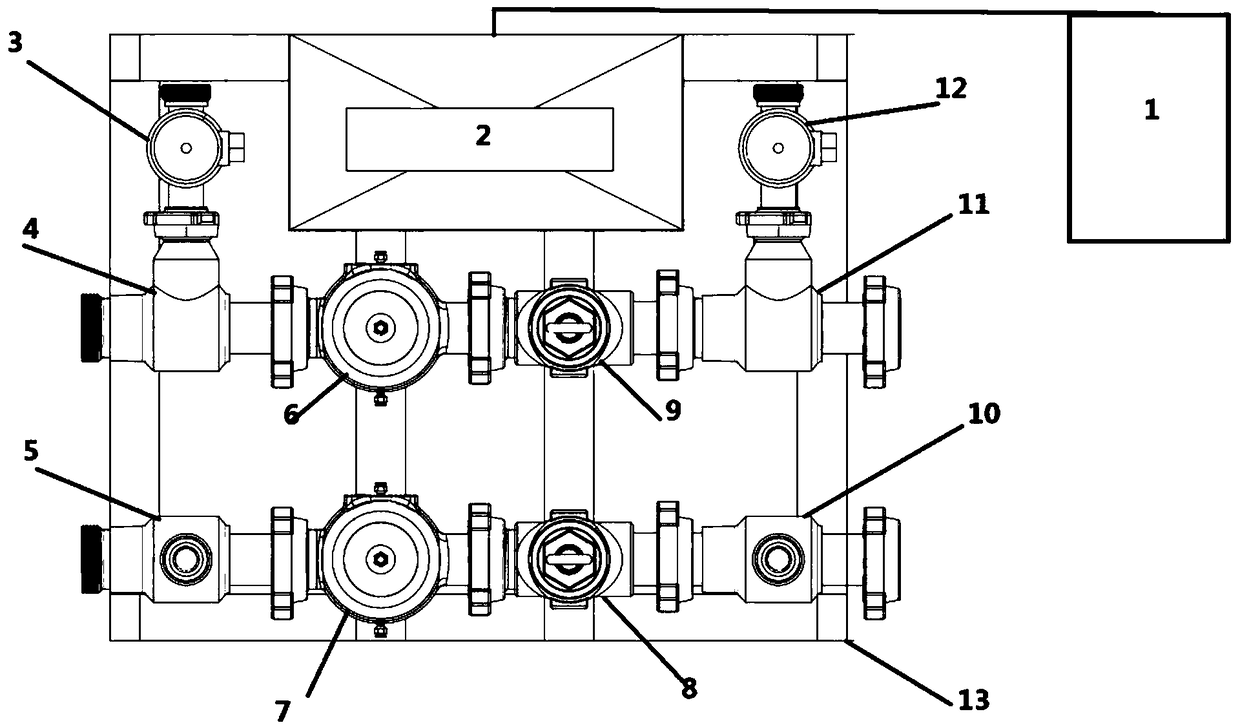
The invention discloses a remote hydraulic dynamic pressure release device and method for a fracturing high-pressure manifold. The remote hydraulic dynamic pressure release device comprises a fracturing high-pressure manifold body, a hydraulic power part and a remote control part; the fracturing high-pressure manifold body comprises a first manifold, a second manifold, a third liquid-controlled plug valve and a fourth liquid-controlled plug valve; the first manifold comprises a first three-way pipe, a first liquid-controlled plug valve, a first single-flow valve and a second three-way pipe which are connected in sequence; the second manifold comprises a third three-way pipe, a second liquid-controlled plug valve, a second single-flow valve and a fourth three-way pipe which are connected insequence; the remote control part is used for sending a control signal to the hydraulic power part, and controlling thefirst liquid-controlled plug valve, the second liquid-controlled plug valve, thethird liquid-controlled plug valve and the fourth liquid-controlled plug valve after the hydraulic power part acts. According to the remote hydraulic dynamic pressure release device and method for the fracturing high-pressure manifold, opening and closing of the liquid-controlled plug valves are remotely controlled to release the internal pressure of the high-pressure manifold, and the difficultproblem that personnel enter the high pressure operation area to open and close the plug valves manually is solved.

Description

technical field [0001] The invention belongs to the field of oilfield fracturing construction, and in particular relates to a remote hydraulic pressure relief device and method for a fracturing high-pressure manifold. Background technique [0002] During oilfield fracturing, the internal pressure of the high-pressure manifold reaches a maximum of 140MPa, and the high-pressure fluid is mixed with quartz sand to wash the inner wall of the pipeline at high speed and high pressure. With the vibration of the equipment during the operation, the manifold may burst unpredictably at any time Therefore, personnel are strictly prohibited from entering the high-pressure operation area during construction. However, after the construction is completed, the interior of the pipeline and the bottom of the well will always maintain a relatively high pressure, and the manifold cannot be removed directly. After the pressure is released and the plug valve is manually pried open, the high-pressur...

Claims


Application Information

Patent Timeline
Patent Type & Authority Applications(China)
IPC IPC(8): E21B43/26E21B34/02F17D1/20F16L55/07
CPCE21B34/02E21B43/26F16L55/07F17D1/20
Inventor 吴竞鸿姜大鹏秦和利尹邦国左威张卫净张钢任四武
Owner 新疆美瑞科石油装备有限公司
Learn More