Eureka AIR delivers breakthrough ideas for toughest innovation challenges, trusted by R&D personnel around the world.

While-drilling testing method and device for coal seam gas parameters

A technology for coal seam gas and testing device, which is applied in drilling equipment and methods, gas discharge, safety devices and other directions, can solve the problems of difficult drilling, inability to adjust the length of the drill bit, cumbersome and other problems, and achieves the effect of good and stable support.

Active Publication Date: 2019-03-01
NORTH CHINA INST OF SCI & TECH
View PDF6 Cites 12 Cited by
  • Summary
  • Abstract
  • Description
  • Claims
  • Application Information

AI Technical Summary

Problems solved by technology

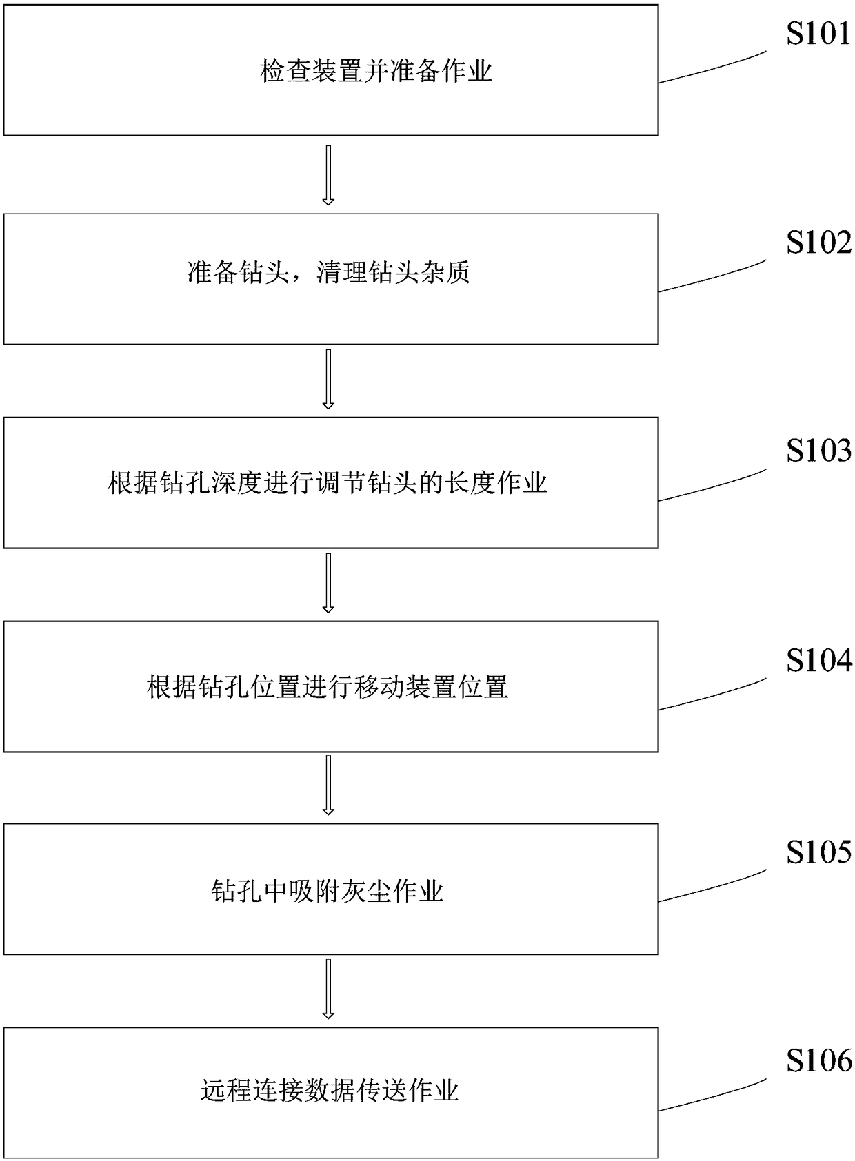
[0005] In order to solve the above technical problems, the present invention provides a coal seam gas parameter testing method and device while drilling, to solve the problem that the existing coal seam gas parameter testing method and device cannot adjust the length of the drill bit to meet the drilling depth requirements. It is easy to generate dust when being drilled, it is not easy to drill when encountering a hard coal seam, the detection data cannot be transmitted over a long distance, and the test operation method is cumbersome. Connecting sleeve, docking shaft, connecting pipe, fastening bolt, straight iron pin, detachable auxiliary drill bit structure for hard coal seam, fixed hex socket socket bolt, length adjustable drilling extension rod structure, auxiliary movement Support transfer frame, dust auxiliary adsorption and anti-splash shield structure when drilling, remote data transmission heat dissipation cover structure, connecting plate and fixed sleeve, and the said hand sleeves are longitudinally socketed in the middle of the outer wall of the hand bar; The longitudinal inner ends of the handrails are respectively welded to the upper and lower parts on the right side of the connecting sleeve; the connecting sleeve is horizontally threaded on the outer wall of the right end of the docking shaft; the horizontal left end of the docking shaft is inserted into the connecting pipe The inner right end of the inner right end is fastened and connected by fastening bolts; the inline iron pin runs through the inner right middle position of the connecting sleeve; the detachable hard coal seam auxiliary drilling bit structure is The socket bolt is installed at the left end of the length-adjustable drilling extension rod structure; the length-adjustable drilling extension rod structure is arranged on the upper end of the auxiliary mobile support transfer frame; the dust auxiliary adsorption anti-splash shield structure during drilling It is arranged on the right part of the length-adjustable drilling extension rod structure; the heat dissipation cover structure capable of remote data transmission is arranged inside the auxiliary mobile support transfer frame; the right part of the connecting plate is connected with a hex socket socket bolt on the fixed sleeve The middle position of the front part; the detachable hard coal seam auxiliary drilling bit structure includes a protective cap, a tapered drill bit, drilling teeth, a diversion groove, a connecting liner and a drill bit body, and the protective cap is threaded At the left end of the tapered drill bit; the drilling teeth are arranged integrally on the upper and lower sides of the outer wall of the tapered drill bit from left to right; the diversion grooves are set horizontally in the middle of the front surface of the tapered drill bit position and the middle position inside the rear surface; one end of the connecting liner is seamlessly welded at the middle position of the left end of the drill body, and the other end is threaded at the left end of the tapered drill bit

Method used


Image

  • While-drilling testing method and device for coal seam gas parameters
  • While-drilling testing method and device for coal seam gas parameters
  • While-drilling testing method and device for coal seam gas parameters

Examples


Embodiment Construction

[0050] The present invention will be further described below in conjunction with accompanying drawing:

[0051] In the picture:

[0052] as attached figure 2 to attach Figure 8 Shown:

[0053] Coal seam gas parameter testing device while drilling, including hand sleeve 1, hand rod 2, connecting sleeve 3, docking shaft 4, connecting pipe 5, fastening bolt 6, in-line iron pin 7, detachable hard coal seam Auxiliary drilling drill bit structure 8, fixed hex socket socket bolt 9, adjustable length drilling extension rod structure 10, auxiliary mobile support transfer frame 11, dust auxiliary adsorption anti-splash shield structure 12 during drilling, remote data transmission and heat dissipation The cover structure 13, the connecting plate 14 and the fixed sleeve 15, the hand sleeves 1 are longitudinally socketed in the middle of the outer wall of the hand bar 2; the longitudinal inner ends of the hand bar 2 are respectively welded to the connecting sleeve The upper and lower...


PUM


Abstract

The invention provides a while-drilling testing method and device for coal seam gas parameters. The while-drilling testingdevice comprises a hand-holdingsleeve, a hand-holdingrod, a connecting casing,a butting shaft, a connecting pipe, fastening bolts, a strip-shaped port iron pin, a removable hard coal seam assisted drilling bit structure, fixed hexagon socket bolts, a drilling extension rod structure with the adjustable length, an auxiliary moving supporting transport frame, a during-drilling dust auxiliary adsorptionsplash-preventing shield structure, a heat dissipating shield structure capable of conducting remote data transmission, a connecting plate and a fixing casing. According to thewhile-drilling testing method and device for the coal seam gas parameters, drilling teeth, a flow-guiding groove, a connection liner pipe and a drill bit body are arranged, coal slag produced during drilling through a cone-shaped bit can be discharged in time through the flow-guiding groove, and the problem of drilled hole blocking is avoided; through the drilling teeth, good auxiliary drilling work can be achieved, and influence of a hard coal seam on deep drilling is avoided; and final reaming operation can be conducted through the drill bit body, and it is ensured that drilling work is conducted smoothly.

Description

technical field [0001] The invention belongs to the technical fields of coal field gas geology, gas / coal bed gas extraction and coal mine safety, and in particular relates to a coal seam gas parameter testing method and device while drilling. Background technique [0002] CBM occurrence, CBM resource assessment, CBM drainage, CBM development, coal seam outburst risk prediction, gas disaster control and effect evaluation all involve coal seam gas parameter testing. At present, parameters such as coal seam gas content are mainly tested by sampling tests. The initial velocity of borehole gas emission is mainly tested in shallow holes on the working face. At present, the method of fixed-point sampling and rapid determination of gas content in coal seams is more accurate, and the sampling process is complicated. Accuracy is greatly affected. At present, the rapid test of coal seam gas content by drilling chip extraction method, which is widely used, has poorer sampling fixed po...

Claims


Application Information

Patent Timeline
Patent Type & Authority Applications(China)
IPC IPC(8): E21B7/02E21B7/28E21B21/015E21B47/12E21B47/06E21B12/04E21F7/00
CPCE21B7/02E21B7/28E21B12/04E21B21/015E21B47/06E21B47/12E21F7/00
Inventor 陈鹏刘永杰李红涛陈学习杨涛谢宏褚廷湘
Owner NORTH CHINA INST OF SCI & TECH
Why Eureka
Eureka Blog
Learn More