Eureka AIR delivers breakthrough ideas for toughest innovation challenges, trusted by R&D personnel around the world.

Concrete hinge joint structure provided with intersecting shearing-resistant reinforcing steel bars and construction method of concrete hinge joint structure

A technology for shearing steel bars and concrete, which is applied in bridge construction, erection/assembly of bridges, bridge parts, etc. It can solve the problems of poor shear resistance and inconvenient construction, and achieve the effects of ensuring comfort, simplifying construction, and low price

Inactive Publication Date: 2019-03-01
CHINA THREE GORGES UNIV
View PDF5 Cites 1 Cited by
  • Summary
  • Abstract
  • Description
  • Claims
  • Application Information

AI Technical Summary

Problems solved by technology

[0004] The technical problem to be solved by the present invention is to provide a concrete hinge joint structure with intersecting shear reinforcement and its construction method, which can solve the problems of poor shear resistance and inconvenient construction, improve the shear resistance of the hinge joint, and greatly simplify construction

Method used


Image

  • Concrete hinge joint structure provided with intersecting shearing-resistant reinforcing steel bars and construction method of concrete hinge joint structure
  • Concrete hinge joint structure provided with intersecting shearing-resistant reinforcing steel bars and construction method of concrete hinge joint structure
  • Concrete hinge joint structure provided with intersecting shearing-resistant reinforcing steel bars and construction method of concrete hinge joint structure

Examples


Embodiment 1

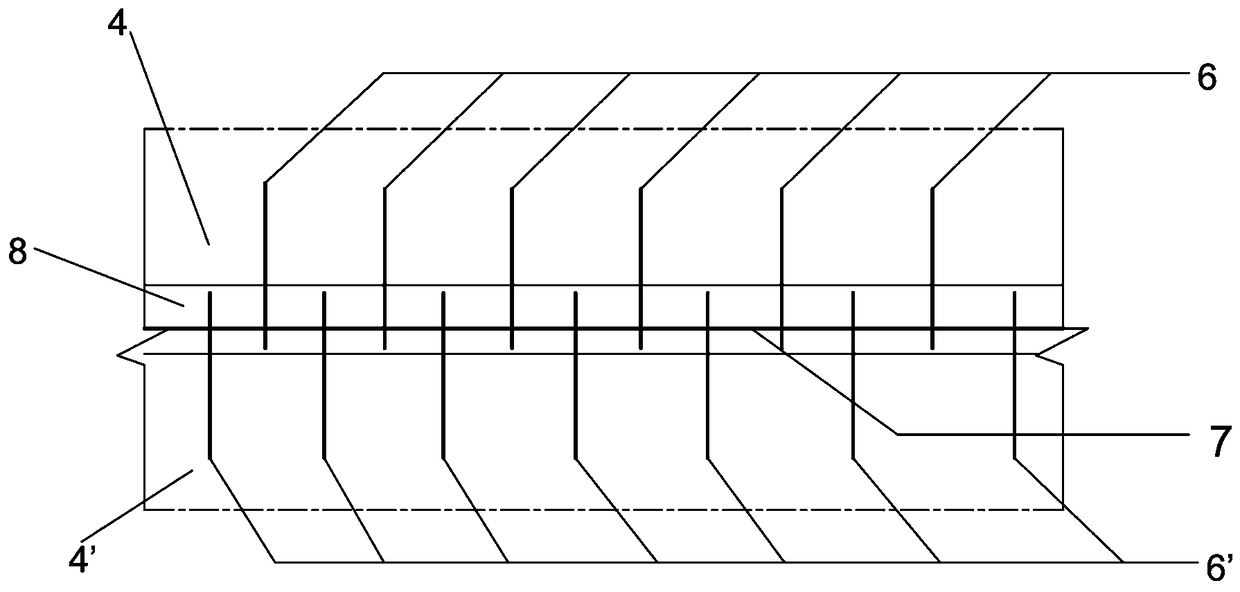
[0036] Such as Figure 1-Figure 3 As shown, a concrete hinged joint structure with intersecting shear reinforcement, including the joint body 8 formed by connecting the bottom of the first hollow slab beam 4 and the second hollow slab beam 4' with bumps 9 on both sides of the bottom, the first The tops of the first hollow slab girder 4 and the second hollow slab girder 4' are evenly arranged with a plurality of horizontal portal steel bars 3, and each horizontal portal steel bar 3 protrudes outward for a certain distance;

[0037] The upper part of the first hollow plate girder 4 is evenly arranged with a plurality of first upper high-strength steel bars 5 inclined upward at a certain angle with the horizontal direction along the extending direction of the hinged body 8, and the upper part of the second hollow plate girder 4' is along the extending direction of the hinged body 8 A plurality of second upper high-strength steel bars 5' inclined upward at a certain angle to the h...

Embodiment 2

[0046] A kind of construction method of above-mentioned hinge joint structure, this method comprises the following steps:

[0047] Step 1: Prefabricate multiple hollow slab beams;

[0048]Step 2: A plurality of transverse portal steel bars 3 are respectively preset on the top of the hollow slab girder, and the horizontal portal steel bars 3 extend a certain distance from the top surface of the hollow slab beam to provide corresponding conditions for the positioning and binding of relevant steel bars in the bridge deck laying layer;

[0049] Step 3: Embedding upper high-strength steel bars in the upper part of each hollow slab beam, and burying lower high-strength steel bars in the lower part of each hollow slab beam, so as to make multiple first hollow slab beams 4 and second hollow slab beams 4';

[0050] Step 4: Hoist the first hollow slab girder 4 and the second hollow slab girder 4' to a predetermined position, and connect the bumps 9 at the bottom of the first hollow slab...


PUM


Abstract

A concrete hinge joint structure provided with intersecting shearing-resistant reinforcing steel bars comprises a hinge joint body formed by connecting the bottoms of a first hollow slab girder and asecond hollow slab girder, wherein protruding blocks are arranged on the two sides of the bottoms of the first hollow slab girder and the second hollow slab girder. The multiple first upper high-strength reinforcing steel bars inclining upwards at a certain angle relative to the horizontal direction are evenly arranged on the upper portion of the first hollow slab girder in the extension directionof the hinge joint body. The multiple second upper high-strength reinforcing steel bars inclining upwards at a certain angle relative to the horizontal direction are evenly arranged on the upper portion of the second hollow slab girder in the extension direction of the hinge joint body. The multiple first lower high-strength reinforcing steel bars are evenly arranged on the lower portion of the first hollow slab girder in the extension direction of the hinge joint body. The multiple second lower high-strength reinforcing steel bars are evenly arranged on the lower portion of the second hollowslab girder in the extension direction of the hinge joint body. By the adoption of the provided concrete hinge joint structure provided with the intersecting shearing-resistant reinforcing steel barsand a construction method of the concrete hinge joint structure, the problems that the shear performance is poor and construction is inconvenient can be solved, the shear capacity of a hinge joint isimproved, and construction is greatly simplified.

Description

technical field [0001] The invention relates to the technical field of bridge construction, in particular to a concrete hinge joint structure with intersecting shear reinforcement and a construction method thereof. Background technique [0002] The hinge joints of existing hollow slab girder bridges are frequently damaged due to defects in design and construction, natural environment and increasing traffic load. Due to the weak reinforcement and filling concrete in the hinge joint and the insufficient shear resistance of the hinge joint, it is easy to have long longitudinal cracks or even cracks under the natural environment and driving load, resulting in water leakage in the hinge joint and damage to the veneer. Damages such as force have greatly affected the applicability and durability of the hollow slab girder, and the current improvement technology often has complicated construction procedures, making it difficult to guarantee the quality of on-site construction. [00...

Claims


Application Information

Patent Timeline
Patent Type & Authority Applications(China)
IPC IPC(8): E01D21/00E01D19/00E01D19/12
CPCE01D19/00E01D19/125E01D21/00
Inventor 刘杰方君潇张杨陈娟娟
Owner CHINA THREE GORGES UNIV
Why Eureka
Eureka Blog
Learn More