


Quick Research
Generate reliable direction feasibility study reports for your R&D in just a few steps.

Technical Q&A
Discover and master advanced knowledge NOW. Basics, ideas, possibilities, all at once.

Find Solutions
As an expert in R&D theories, this can generate solutions to your technical problems instantly.

Evaluate Feasibility
Analyze your overall solution with one click, know your potential R&D risks in advance.

Monitor Landscape
Get weekly tech updates, stay abreast of the latest tech innovations and key insights.
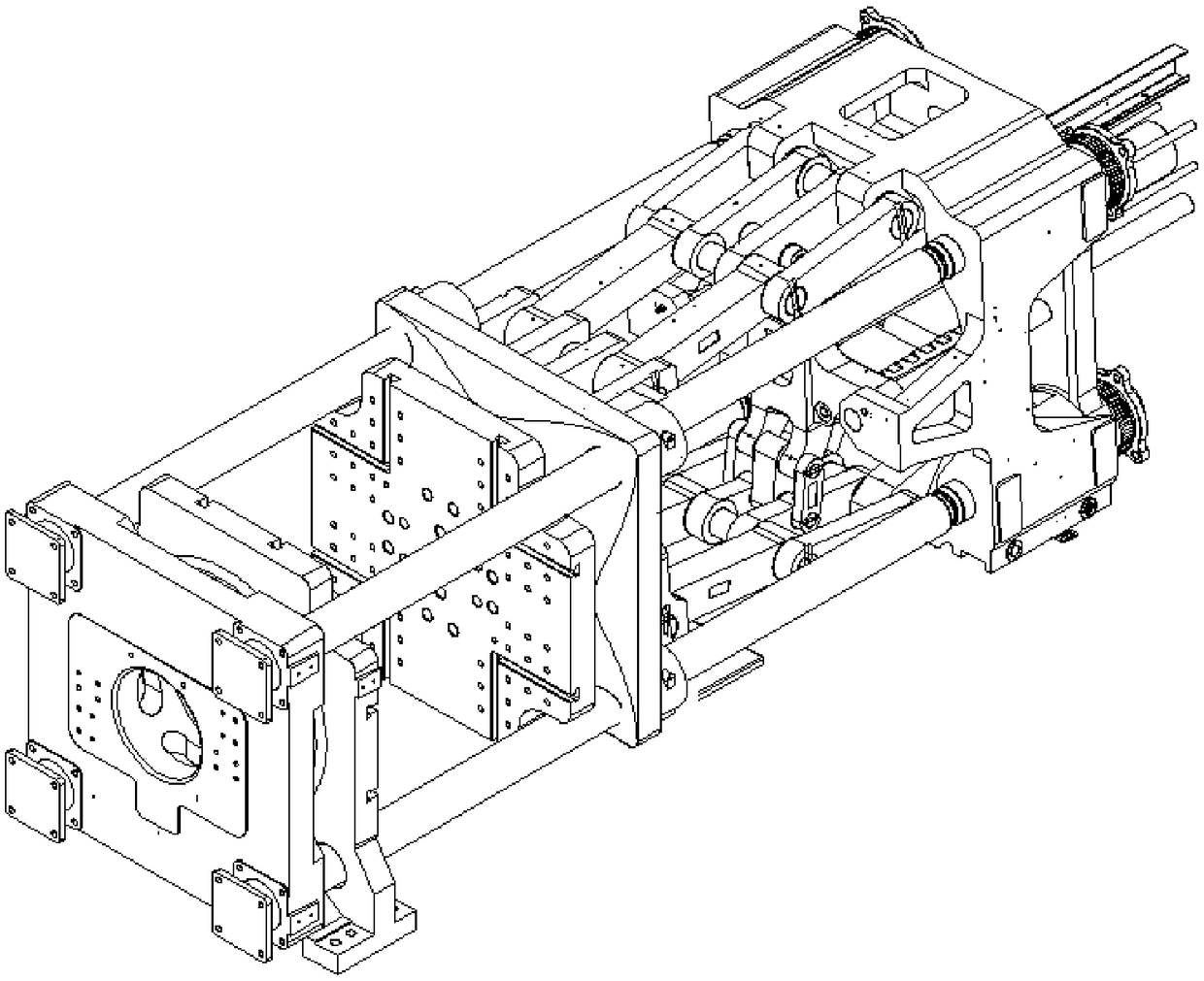
Mold combining mechanism of injection machine
A mold clamping mechanism and injection machine technology, applied in the field of injection molding machines, can solve problems such as uneven distribution of long-term clamping force, affecting the quality of injection molded products, poor exhaust, etc., to achieve light weight, reduce deformation, and improve utilization. Effect
- Summary
- Abstract
- Description
- Claims
- Application Information
AI Technical Summary
Problems solved by technology
Method used
Image

Examples
Embodiment Construction
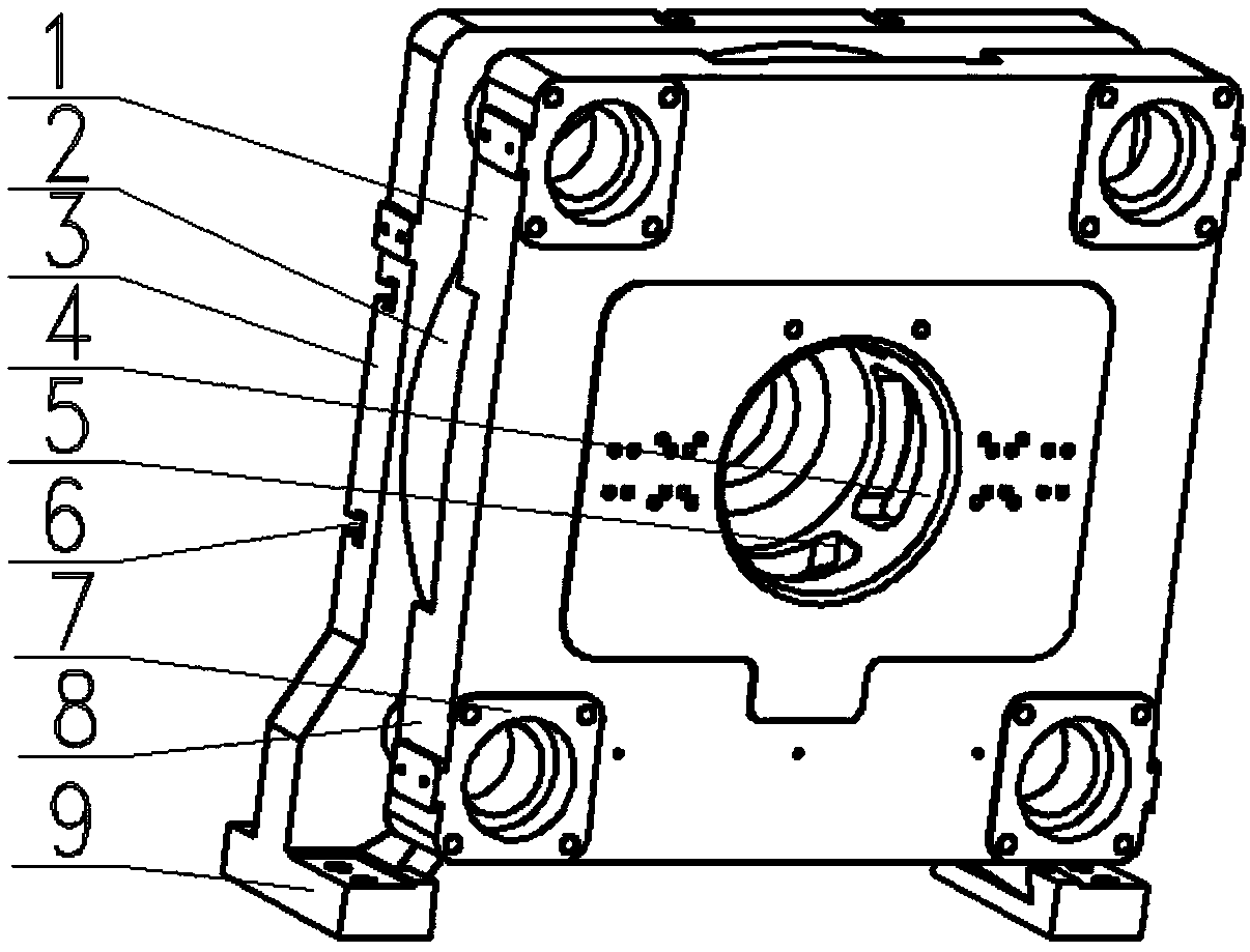
[0022] A mold clamping mechanism of an injection machine of the present invention, such as image 3 , 4 , 5, 6, and 7, including mold clamping mechanism, front template and movable template, front template plate includes front template clamping force loading plate 1, front template annular hollow arc surface support 2, front template mold mounting plate 3, dynamic The template includes a movable template mold mounting plate 10 , a movable template annular hollow arc surface support 11 and a movable template clamping force loading plate 12 . Among them, there are tie rod guide seats 7 at the four corners of the front formwork clamping force loading plate 1, and support feet 9 are provided under the front formwork. There are tie rod holes 14 at the four corners of the loading plate 12, the lower surface of the movable template clamping force loading plate 12 is connected with the annular hollow arc surface support 11 of the movable template, and there is a sliding foot 13 of th...
PUM
 Abstract
Description
Claims
Application Information
 - R&D Engineer
- R&D Manager
- IP Professional
- Industry Leading Data Capabilities
- Powerful AI technology
- Patent DNA Extraction
Browse by: Latest US Patents, China's latest patents, Technical Efficacy Thesaurus, Application Domain, Technology Topic, Popular Technical Reports.
© 2024 PatSnap. All rights reserved.Legal|Privacy policy|Modern Slavery Act Transparency Statement|Sitemap|About US| Contact US: help@patsnap.com