Bridge construction equipment

A kind of equipment and bridge technology, which is applied in the field of bridge construction equipment, can solve the problems of inconvenient use, time-consuming, laborious and bulky use, and achieve the effect of improving work efficiency

Inactive Publication Date: 2019-02-26
韦红生
View PDF0 Cites 0 Cited by
  • Summary
  • Abstract
  • Description
  • Claims
  • Application Information

AI Technical Summary

Problems solved by technology

[0002] In the process of bridge construction, a large amount of marl is needed to make concrete. The existing concrete mixer pours out all the concrete at one time after mixing, and cannot accurately control the amount of concrete poured out. Moreover, the existing concrete mixers are relatively heavy. , the operation is not flexible enough, it is inconvenient to use, and it is time-consuming and laborious to use

Method used


Image

  • Bridge construction equipment
  • Bridge construction equipment
  • Bridge construction equipment

Examples


Embodiment Construction

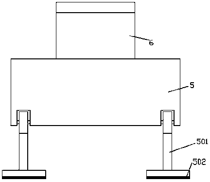
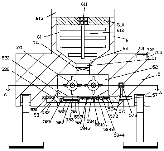
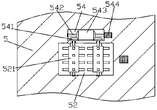
[0026] Such as Figure 1-Figure 6 As shown, a bridge construction equipment of the present invention includes a processing base 5 and a stirring box 6 installed on the top of the processing base 5, the stirring box 6 is provided with a stirring chamber 61, and the bottom of the stirring chamber 61 A guide cavity 62 extending downward is provided through the passage, and the extended section at the bottom of the guide cavity 62 penetrates into the processing base 5. The bottom end of the guide cavity 62 is penetrated with a soil discharge port 51, and the processing The bottom surface of the base 5 is provided with a soil discharge groove 52 which is arranged on the top and the bottom end of the soil discharge port 51. The inner walls of the left and right sides of the soil discharge groove 52 are provided with sliding joint grooves 53 correspondingly, and each of the sliding joints The inner top wall of the groove 53 is provided with a guide groove 532, and the sliding groove ...


PUM


Abstract

The invention discloses bridge construction equipment, which comprises a processing base and a stirring box installed on the top portion of the processing base, wherein a stirring chamber is arrangedin the stirring box, a downward extending connection guide chamber penetrates through the bottom portion of the stirring chamber, the extending section of the bottom portion of the connection guide chamber extends into the processing base, the bottom end of the connection guide chamber is provided with a soil discharge port in a penetrating manner, a soil discharge groove is arranged in the bottomsurface of the processing base, the top portion of the soil discharge groove penetrates through the bottom end of the soil discharge port, sliding connection grooves are symmetrically arranged on theinner walls of the left side and the right side of the soil discharge groove, the inner-top walls of each sliding connection groove are respectively provided with a connection guide groove, a processing penetrating through the soil discharge groove is slidingly connected between the left sliding connection groove and the right sliding connection groove, and the top portions of the left end and the right end of the processing device in the left sliding connection groove and the right sliding connection groove are slidingly connected to guide blocks extending into the left sliding connection groove and the right sliding connection groove. According to the present invention, the bridge construction equipment has characteristics of simple structure, convenient operation, automatic control ofdifferent concrete amounts, and working efficiency improving.

Description

technical field [0001] The invention relates to the field of bridges, in particular to bridge construction equipment. Background technique [0002] In the process of bridge construction, a large amount of marl is needed to make concrete. The existing concrete mixer pours out all the concrete at one time after mixing, and cannot accurately control the amount of concrete poured out. Moreover, the existing concrete mixers are relatively heavy. , the operation is not flexible enough, it is inconvenient to use, and it is time-consuming and laborious to use. Contents of the invention [0003] The technical problem to be solved by the present invention is to provide a bridge construction equipment, which can solve the above-mentioned problems in the prior art. [0004] The present invention is achieved through the following technical solutions: a bridge construction equipment of the present invention includes a processing base and a stirring box installed on the top of the proce...

Claims


Application Information

Patent Timeline
Patent Type & Authority Applications(China)
IPC IPC(8): B28C5/08B28C5/14B28C5/16
CPCB28C5/0875B28C5/0818B28C5/0831B28C5/146B28C5/148B28C5/16
Inventor 王泽华
Owner 韦红生
Why Eureka
Try Eureka