
A control method and device for reducing programming interference

A technology of programming interference and control method, applied in the field of memory devices, can solve problems such as failure to achieve expected results, difficulty in reaching voltage, and insufficient precharge.

Active Publication Date: 2019-02-22
长存创芯(上海)集成电路有限公司
View PDF9 Cites 10 Cited by
  • Summary
  • Abstract
  • Description
  • Claims
  • Application Information

AI Technical Summary

Problems solved by technology

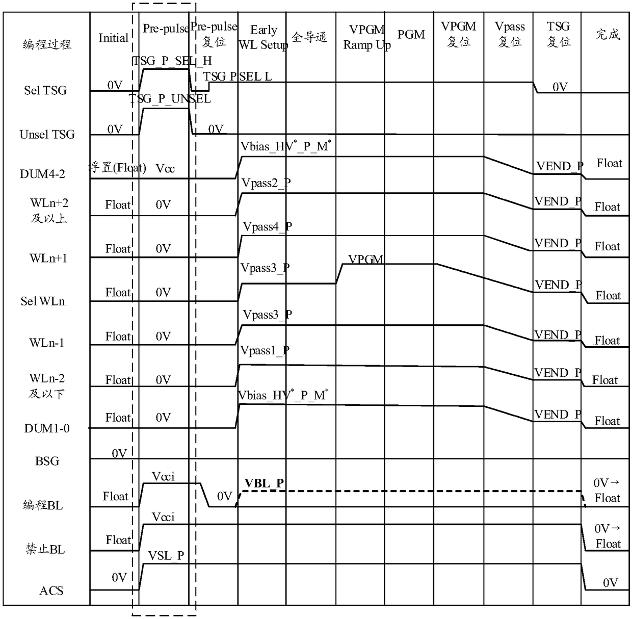
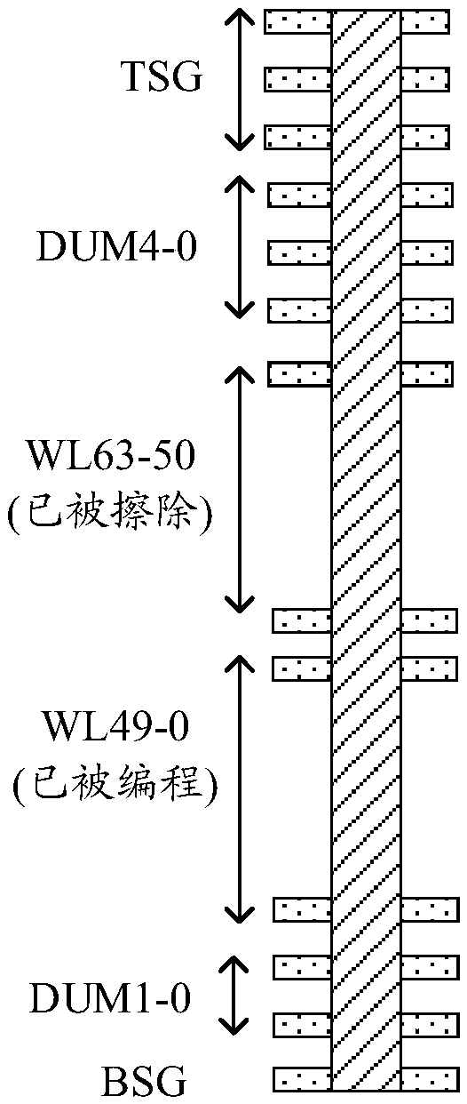
However, this method has certain disadvantages. For example, due to the existence of programmed memory cells, it is difficult for the voltage precharged from the drain terminal to reach the memory cells near the source terminal, which will lead to insufficient precharge and fail to achieve the expected Effect

Method used


Image

  • A control method and device for reducing programming interference
  • A control method and device for reducing programming interference
  • A control method and device for reducing programming interference

Examples


Embodiment 1

[0067] like Figure 4 As shown, the control method for reducing programming disturb provided by Embodiment 1 of the present invention is a control method for performing precharging from both sides of the drain terminal and the P well terminal at the same time. The arrows in the figure show the direction of hole injection.

[0068] combine Figure 5 It can be seen that in this embodiment, in the pre-charging stage of the storage device (that is, the stage of loading the pre-pulse Pre-pulse in the figure), the top gate TSG0-5 is loaded with a high potential that can be turned on by TSG0-5; The power supply potential Vcc is loaded on the BL, so that holes are injected into the channel hole from the drain terminal, and the potential of the channel hole is increased. At the same time, the bottom gate BSG is connected to the ground potential GND, and the power supply potential Vcc is applied to the Pwell; since the potential GND of the bottom gate BSG is lower than the potential V...

Embodiment 2

[0072] like Image 6 As shown, the control method for reducing program disturb provided by Embodiment 2 of the present invention is a control method for precharging only from the P-well terminal. The arrows in the figure show the direction of hole injection.

[0073] combine Figure 7 It can be seen that in this embodiment, in the precharging stage of the storage device (that is, the stage of applying the pre-pulse Pre-pulse in the figure), the bottom gate BSG is connected to the ground potential GND, and a bias voltage higher than the power supply potential is applied to the Pwell. Position bias; since the bottom gate BSG potential GND is lower than the Pwell potential bias, holes in the Pwell are injected into the channel holes. At the same time, the top gate TSG0-5 is grounded, so that the top gate is in a closed state; the bit line BL is floating (Float).

[0074] Here, the precharged voltage at the P-well terminal may not be affected by the bit line terminal (ie, the d...


PUM


Abstract

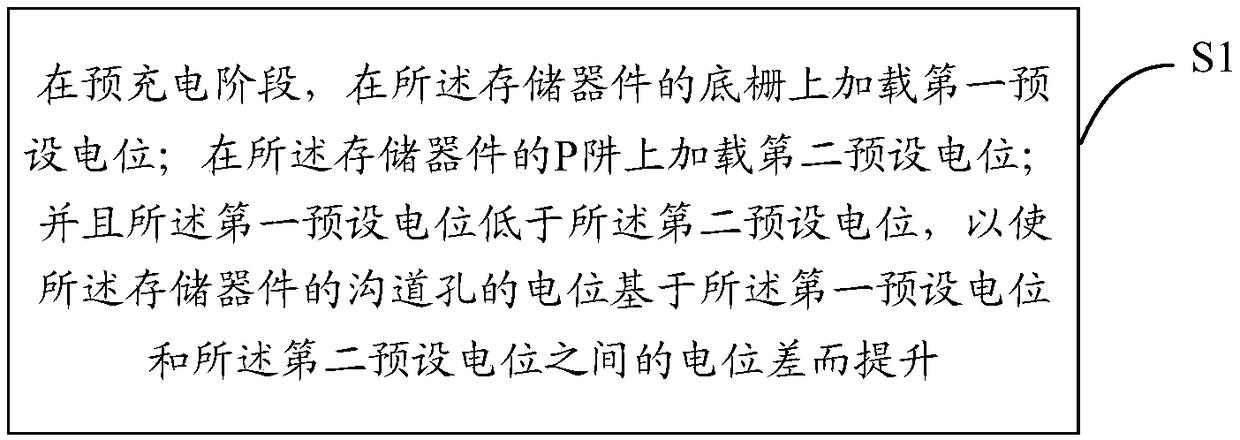
The invention discloses a control method for reducing programming interference. The method is applied to a memory device. The method comprises the following steps: a first preset potential is loaded on a bottom gate of the memory device in a precharging stage; a second preset potential is loaded on the P well of the memory device; And the first preset potential is lower than the second preset potential so that a potential of a channel hole of the memory device is raised based on a potential difference between the first preset potential and the second preset potential.

Description

technical field [0001] The present invention relates to the technical field of storage devices, in particular to a control method and device for reducing programming interference. Background technique [0002] A flash memory device (Flash Memory) is a non-volatile storage device, which can still maintain the stored data information in the case of power failure. A cell array of a flash memory device includes a plurality of memory cell blocks, each memory cell block includes a plurality of cell strings, and each cell string has a channel hole perpendicular to the substrate. [0003] The channel hole potential of the flash memory device is a key parameter to realize the program shutdown operation. In the programming operation, the first step is the pre-charging step. The purpose of this pre-charging step is to increase the potential of the channel hole, so that the potential of the channel hole can be raised higher during the pulse period, and the programming disturbance is sm...

Claims


Application Information

Patent Timeline
Patent Type & Authority Applications(China)
IPC IPC(8): G11C16/34G11C16/30
CPCG11C16/30G11C16/3418
Inventor 梁轲侯春源
Owner 长存创芯(上海)集成电路有限公司
Learn More