
Device and method for detecting railway vehicle brake clamp unit

A brake caliper and railway vehicle technology, applied in the field of rail transit, can solve problems such as non-unique position, processing and assembly errors, and inability to accurately evaluate the performance of the brake caliper unit, so as to improve accuracy and eliminate the gap between connecting pairs Effect

Pending Publication Date: 2019-02-22
CHINA ACADEMY OF RAILWAY SCI CORP LTD +3
View PDF0 Cites 2 Cited by
  • Summary
  • Abstract
  • Description
  • Claims
  • Application Information

AI Technical Summary

Problems solved by technology

[0003] But present test method or detection device mainly have the following deficiencies: 1, the distance problem between the brake pad and the brake disc
The brake pads of the brake caliper unit rotate around its fixed axis, and the position is not unique during the test process. The displacement of the same brake caliper unit is inconsistent in multiple tests, and the displacement change is inconsistent in multiple tests, so it is impossible to accurately evaluate the brake caliper unit. performance
2. The internal connection pair of the brake caliper unit has a great influence on the distance between the test brake pad and the brake disc, which also causes the location of the test process to be not unique, and the performance of the brake caliper unit cannot be accurately evaluated
3. There are processing and assembly errors in the brake caliper unit and the test device. At the same time, the error is objective and unavoidable. Therefore, when testing the brake caliper unit, the inaccurate installation position causes the brake caliper unit brake shoe support If it is not perpendicular to the force sensor, the above situation will cause the loss of force measurement, and the braking force cannot be accurately evaluated

Method used


Image

  • Device and method for detecting railway vehicle brake clamp unit
  • Device and method for detecting railway vehicle brake clamp unit
  • Device and method for detecting railway vehicle brake clamp unit

Examples


Embodiment Construction

[0036]The details of the present invention can be understood more clearly with reference to the accompanying drawings and the description of specific embodiments of the present invention. However, the specific embodiments of the present invention described here are only for the purpose of explaining the present invention, and should not be construed as limiting the present invention in any way. Under the teaching of the present invention, the skilled person can conceive any possible modification based on the present invention, and these should be regarded as belonging to the scope of the present invention. It should be noted that when an element is referred to as being “disposed on” another element, it may be directly on the other element or there may also be an intervening element. When an element is referred to as being "connected to" another element, it can be directly connected to the other element or intervening elements may also be present. The terms "mounted", "connect...


PUM


Abstract

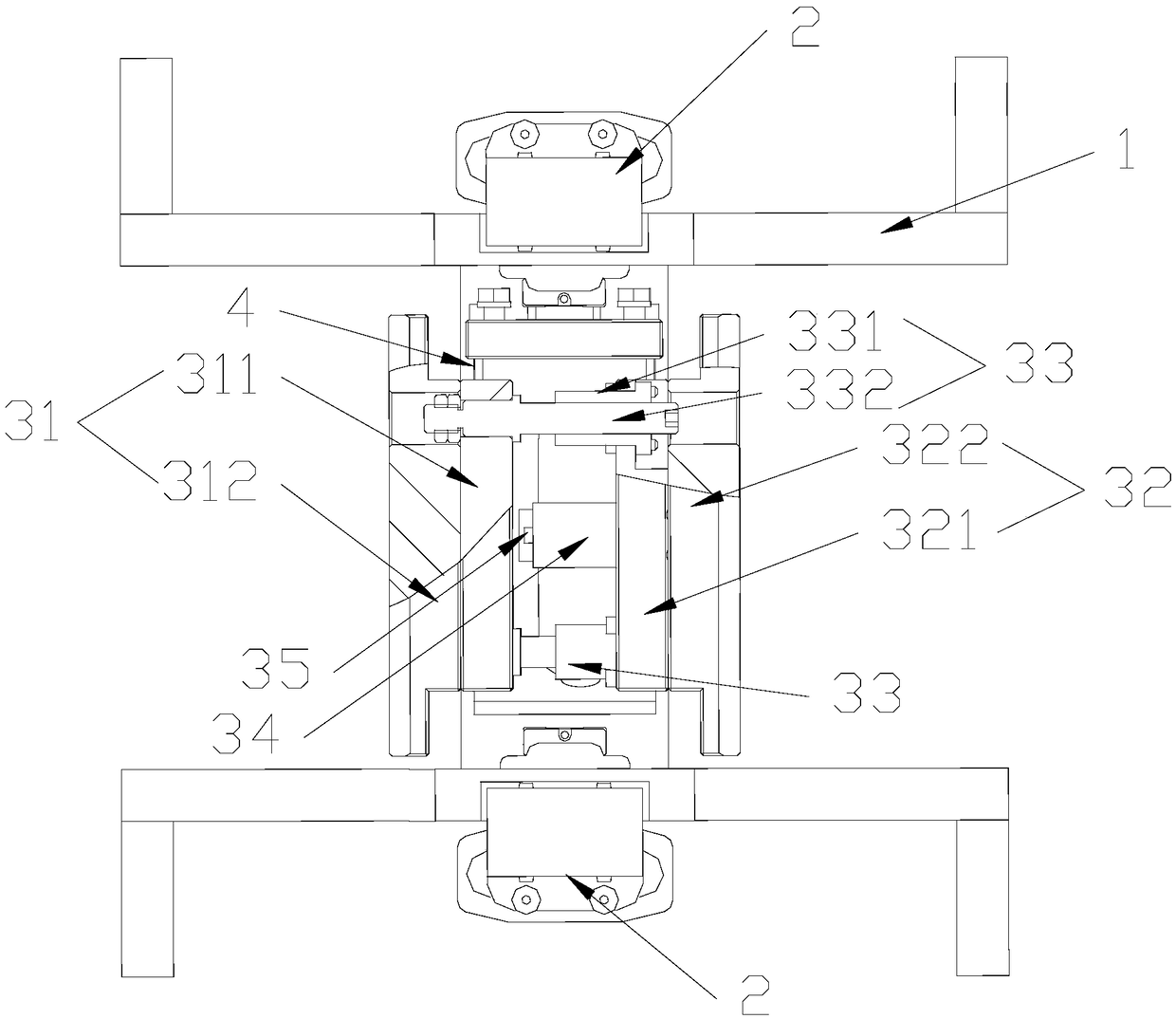
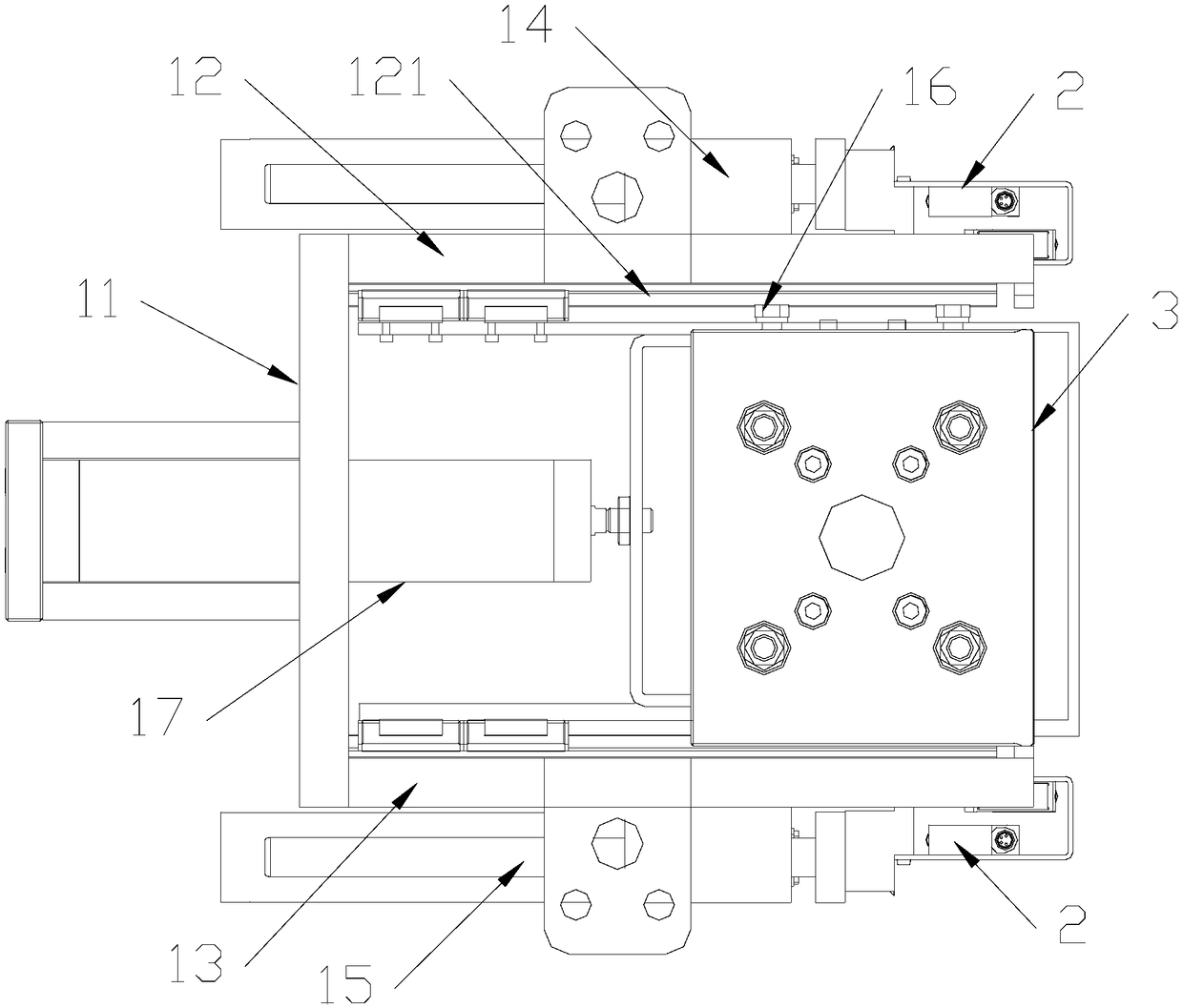
The invention discloses a device and method for detecting a railway vehicle brake clamp unit and relates to the technical field of rail transit. The device comprises a bracket mechanism, a plurality of displacement sensors installed on the bracket mechanism, and a clamping force measuring mechanism which is connected to the bracket mechanism by a rope body such that the clamping force measuring mechanism can swing freely. The clamping force measuring mechanism comprises a first dummy disc and a second dummy disc which are oppositely arranged, multiple shaft units which are installed on the first dummy disc and the second dummy disc and can allow the first dummy disc and the second dummy disc to generate translation in mutually facing directions, a first cylinder arranged between the firstdummy disc and the second dummy disc, and a force sensor for measuring the clamping force between the first dummy dis and the second dummy disc. According to the device, the first dummy disc and the second dummy disc can run oppositely along the shaft units under the effect of the first cylinder such that the first dummy disc and the second dummy disc generate a relative distance change while theparallelism of the first dummy disc and the second dummy disc are maintained, and therefore, the accuracy of a test is effectively improved.

Description

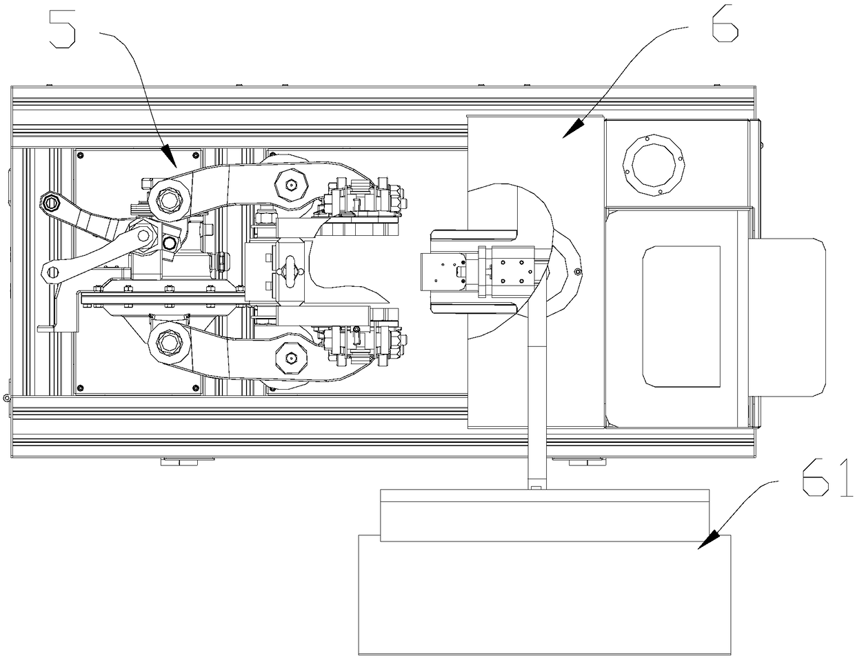
technical field [0001] The invention relates to the technical field of rail transit, in particular to a detection device and a detection method for a brake caliper unit of a railway vehicle. Background technique [0002] In the basic braking of railway vehicles, one of the braking methods is to clamp the brake disc mounted on the axle through the brake caliper unit to achieve the braking effect. Its structure is similar to that of the attached image 3 Brake caliper units for railway vehicles. The brake caliper unit mainly has two control parameters, the distance between the brake pad and the brake disc and the braking force. These two parameters have an important influence on the braking effect of the railway vehicle. In the existing detection methods or detection devices, the laser displacement sensor is generally installed between the brake pad holders of the brake caliper unit through a mechanical structure, and the displacement variation of the brake pad holders (that i...

Claims


Application Information

Patent Timeline
Patent Type & Authority Applications(China)
IPC IPC(8): G01M17/08
CPCG01M17/08
Inventor 白旺旺王苏敬钱晨余欲为
Owner CHINA ACADEMY OF RAILWAY SCI CORP LTD
Learn More