
Energy-feedback suspension system

A suspension system and energy-feeding technology, which is applied in the field of energy-feeding suspension systems, can solve the problems that the energy-feeding suspension cannot efficiently recover vibration energy and the performance of individual certificates is not good, so as to improve the handling stability and driving comfort, The effect of improving comprehensive performance and excellent vibration isolation performance

Pending Publication Date: 2019-02-22
CHANGZHOU INST OF MECHATRONIC TECH
View PDF5 Cites 0 Cited by
  • Summary
  • Abstract
  • Description
  • Claims
  • Application Information

AI Technical Summary

Problems solved by technology

[0004] The present invention solves the problem that the energy-feeding suspension in the prior art cannot efficiently recycle vibration energy and at the same time has poor performance, and provides an energy-feeding suspension system, which is different from the existing energy-feeding suspension system and can efficiently Realize the recovery of suspension vibration energy, and at the same time have excellent vibration isolation performance, improve the handling stability and driving comfort of the vehicle

Method used


Image

  • Energy-feedback suspension system
  • Energy-feedback suspension system
  • Energy-feedback suspension system

Examples


specific Embodiment approach 1

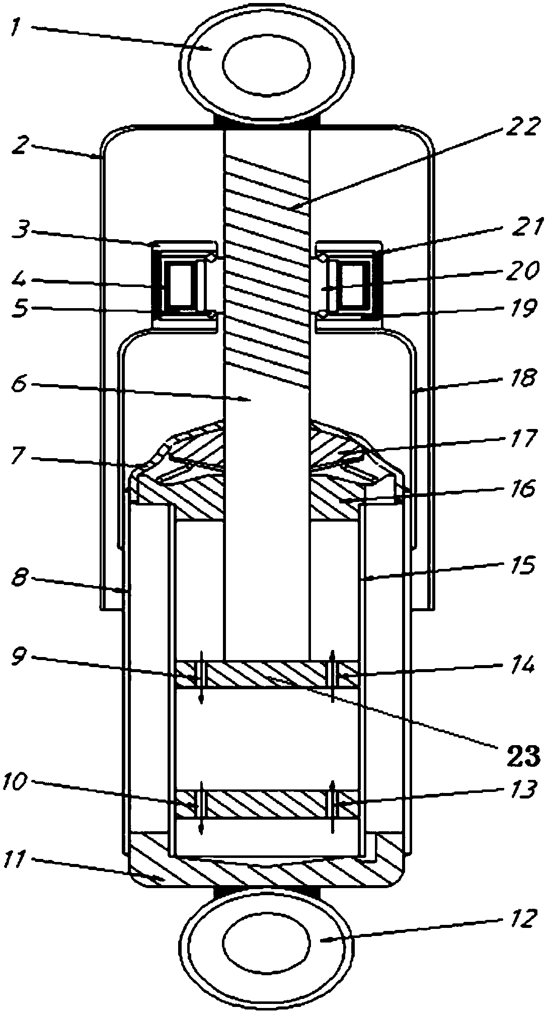
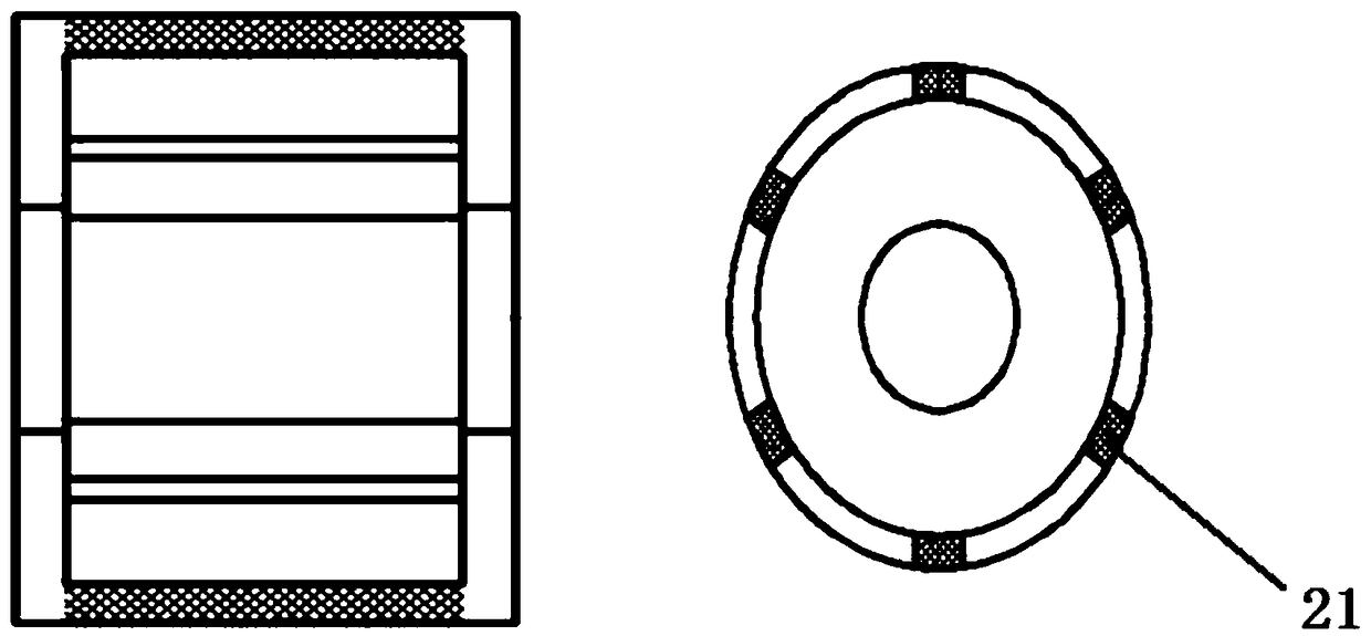
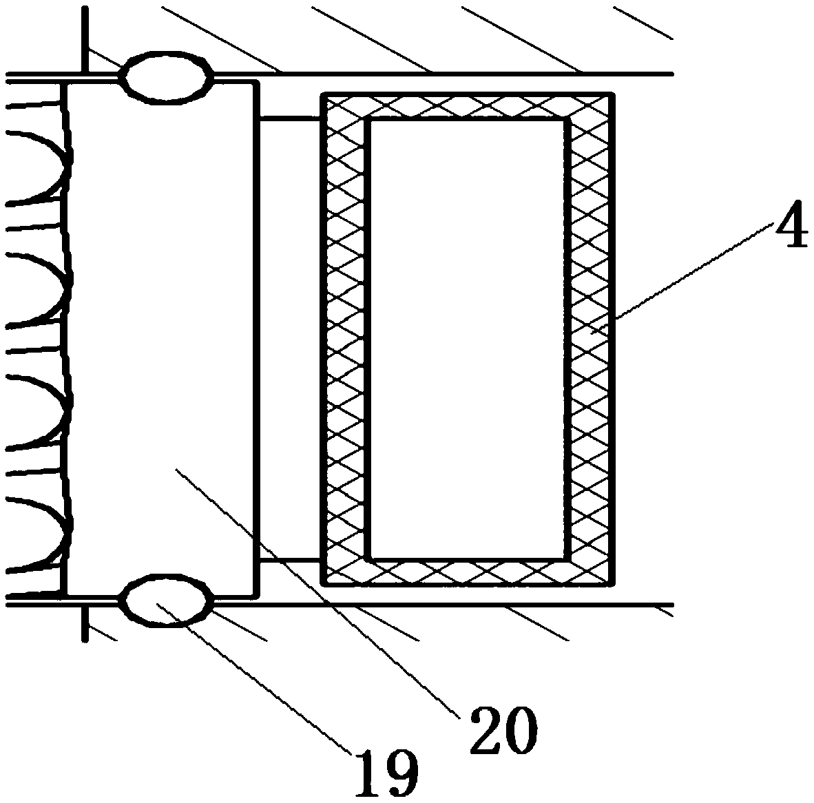
[0023] Specific implementation mode one: see Figure 1-Figure 4 This embodiment will be described. The energy-feeding suspension system described in this embodiment includes an upper suspension ring 1, a dust cover 2, a permanent magnet frame 3, a coil winding 4, a piston rod 6, a piston 23, a sealing cover 7, an oil storage barrel 8, an extension valve 9, Compression valve 10, bottom cover 11, lower lifting ring 12, compensation valve 13, flow valve 14, working cylinder 15, guide 16, oil seal 17, bracket cylinder 18, stopper 19, lead screw nut 20, permanent magnet 21 and ball Lead screw 22; the top of the dust cover 2 is equipped with an upper ring 1, the axial middle position in the dust cover 2 is equipped with a piston rod 6, and the top of the piston rod 6 is set as a screw structure 22, The outer periphery of the screw structure 22 is covered with a lead screw nut 20, the upper and lower ends of the lead screw nut 20 are equipped with stoppers 19, the outer periphery of...


PUM

PropertyMeasurementUnit
Diameteraaaaaaaaaa
Lengthaaaaaaaaaa

Abstract

The invention discloses an energy-feedback suspension system. A piston rod is axially installed inside a dustproof hood of the energy-feedback suspension system; the upper part of the piston rod is ofa screw structure; the outer circumference of the screw structure is sleeved with a screw nut; stop blocks are correspondingly installed at the upper and lower ends of the screw nut; a permanent magnetic iron frame is installed at the outer circumference of the screw nut; a permanent magnet is installed inside the permanent magnetic iron frame; a coil winding is installed between the permanent magnetic iron frame and the screw nut; an outer ring of an oil storage bucket is fixedly connected with a bracket cylinder used for supporting the permanent magnetic iron frame; a piston is installed atthe bottom end of the piston rod; the piston is provided with a rebound valve and a flow valve; an end plate is installed at the lower part of a working cylinder; a compression valve and a compensation valve are installed on the end plate; the compression valve is positioned under the rebound valve; and the compensation valve is positioned under the flow valve. The energy-feedback suspension system solves the problems that an energy-feedback suspension of the prior art is incapable of efficiently recycling vibration energy and meanwhile the vibration isolation performance is not good; the energy-feedback suspension system provided by the invention can realize efficient recycle of the vibration energy of the suspension, also has excellent vibration isolation performance and improves the operation stability and the running smoothness of a vehicle.

Description

technical field [0001] The invention relates to an energy-feeding suspension system, which belongs to the technical field of automobile suspension. Background technique [0002] In recent years, domestic and foreign scholars have not only focused on improving the vibration isolation performance of the suspension, but also paid more attention to the energy recovery of the suspension during the vibration process. Under this background, the concept of energy-feeding suspension came into being. [0003] The "energy feed" in the energy feed suspension system refers to the concept of energy recovery, which can not only effectively block the transmission of vibration, but also recover the energy in the vibration process. However, the research on the energy-feeding suspension is still in the stage of theoretical research and experimental testing, and no energy-feeding suspension has been put into commercial market operation. In particular, the electromagnetic energy-feeding suspens...

Claims


Application Information

Patent Timeline
IPC IPC(8): B60G13/18F03G7/08
CPCF03G7/08B60G13/18
Inventor 张红党杨宏图沈钰杰戴瑞学王峰
Owner CHANGZHOU INST OF MECHATRONIC TECH
Learn More