
Electric displacement setting-out device and lofting method of heteromorphic spiral body intersecting line

A technology of electric displacement and helix, which is applied in the direction of workshop equipment and manufacturing tools, can solve the problems of inaccurate positioning and affecting installation accuracy, and achieve the effect of ensuring the accuracy of lofting, reducing construction costs, and reducing labor difficulty

Active Publication Date: 2019-02-22
CHINA FIRST METALLURGICAL GROUP
View PDF13 Cites 2 Cited by
  • Summary
  • Abstract
  • Description
  • Claims
  • Application Information

AI Technical Summary

Problems solved by technology

However, the process steel structure welding is usually placed on the rotating tire. The above-mentioned intersecting line expansion pattern plate lofting technology needs to avoid the rotating tire. Segmentation and relay lofting on the surface of the helical body will easily cause inaccurate positioning and affect the installation accuracy.

Method used


Image

  • Electric displacement setting-out device and lofting method of heteromorphic spiral body intersecting line
  • Electric displacement setting-out device and lofting method of heteromorphic spiral body intersecting line
  • Electric displacement setting-out device and lofting method of heteromorphic spiral body intersecting line

Examples


Embodiment Construction

[0039] In order to have a clearer understanding of the technical features, purposes and effects of the present invention, the specific implementation manners of the present invention will now be described in detail with reference to the accompanying drawings.

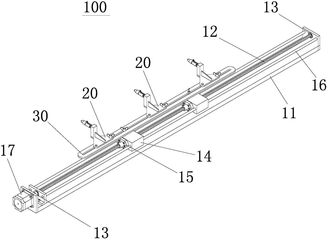
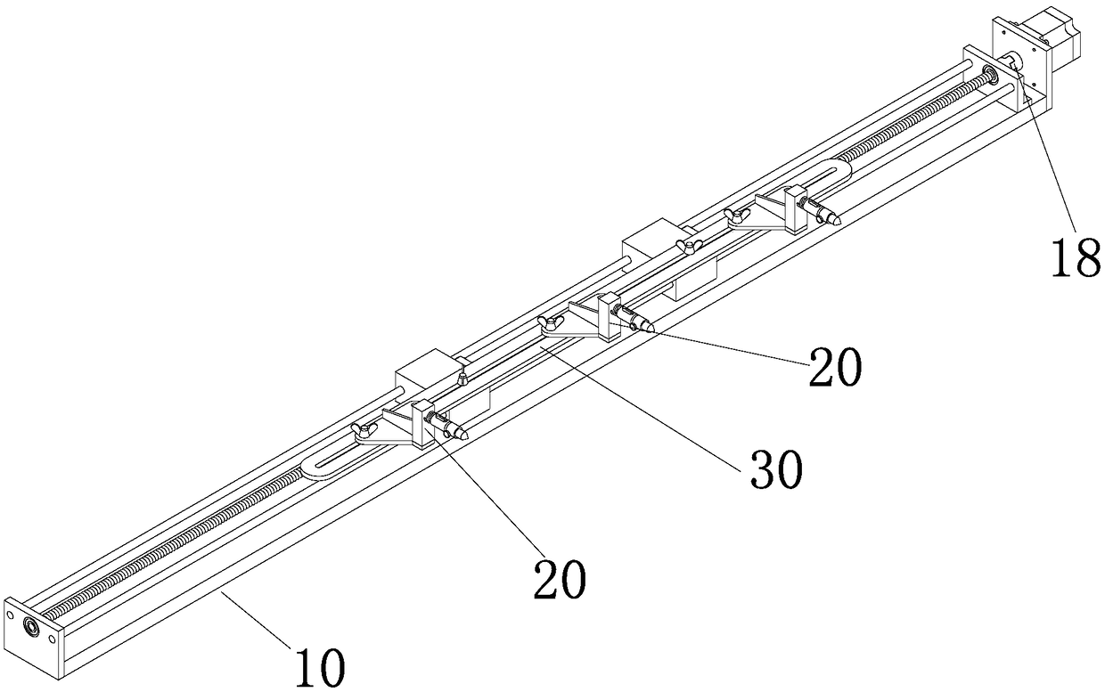
[0040] Such as Figure 1-4 As shown, it is an electric displacement line drawing device 100 according to a preferred embodiment of the present invention, which includes a screw slide 10 and at least one line drawing mechanism 20 installed on the screw slide 10. The screw slide 10 according to the displacement information With the drawing line mechanism 20 moves the drawing line. The line-drawing mechanism 20 is an adaptive adjustment structure, including a base plate 21, a bracket 22, a fixed rod 23, a rod cover 24, a spring 26, and a nib 29. One end of the base plate 21 is vertically mounted with a bracket 22, and the upper end of the bracket 22 is horizontally mounted with a cylinder. fixed rod 23, the fixed rod 23 i...


PUM


Abstract

The invention relates to an electric displacement setting-out device and a lofting method of a heteromorphic spiral body intersecting line. The electric displacement scoring device comprises a screw rod sliding platform and one or more setting-out mechanisms mounted on the screw rod sliding platform, wherein the screw rod slipway is used for driving the setting-out mechanism to move and score according to displacement information; each setting-out mechanism adopts a self-adapting control structure, and comprises a bottom plate, a bracket, a fixing rod, a rod sleeve, a spring and a pen head; each bracket is vertically mounted at one end of the corresponding bottom plate; each fixing rod is horizontally mounted at the upper end of the corresponding bracket; each rod sleeve is arranged on thecorresponding fixing rod in a sleeving manner; each pen head is mounted at the front end of the corresponding rod sleeve; and each spring is arranged between the corresponding rod sleeve and the corresponding bracket, and is arranged on the corresponding fixing rod in a sleeving manner. The method disclosed by the invention adopts the setting-out device for lofting, so that the problems of a conventional two-dimensional three-view setting-out method is tedious in steps, and requirements for space imagination capacity and orthographic view reading level of constructors are high, are avoided, and the problems that when an intersecting line of a large-diameter circular pipe placed on a positioner is lofted, avoiding the positioner is needed, and during section relay lofting on the surface ofthe circular pipe, positioning is easy to be inaccurate, and the construction and the mounting accuracy are influenced, are solved.

Description

technical field [0001] The invention relates to the technical field of complex steel structure construction, in particular to an electric displacement line drawing device and a method for setting out intersecting lines of special-shaped spiral bodies. Background technique [0002] In the construction of steel structures, the intersection line of the surfaces of two spatial shapes is called the intersecting line. The shape design of the process steel structure special-shaped spiral gate has many joints between curved surfaces, positioning, blanking, rolling, and production are troublesome, and the precision requirements are relatively high. The stakeout method of the intersecting line of the special-shaped helix is ​​divided into stakeout on the plane and stakeout on the curved surface: [0003] (1) Stakeout on the plane: First, through the three views of the orthographic projection (front view, top view, left view Figure three basic view), divide the helix circumference in...

Claims


Application Information

Patent Timeline
Patent Type & Authority Applications(China)
IPC IPC(8): B25H7/04
CPCB25H7/045
Inventor 夏春剪元香郑运洪
Owner CHINA FIRST METALLURGICAL GROUP
Learn More