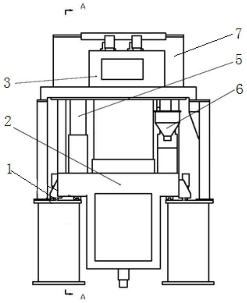
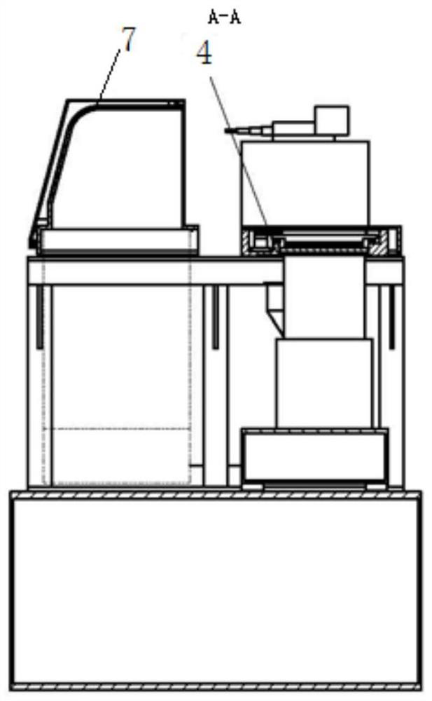
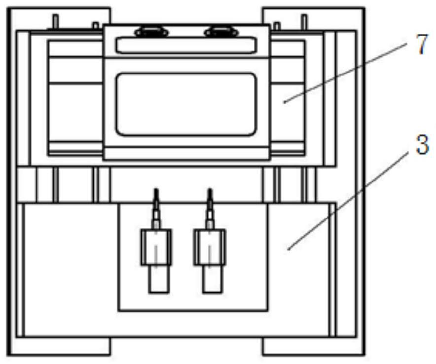
A laser selective melting forming equipment
A technology of laser selective melting and forming equipment, which is applied in the direction of process efficiency improvement, additive manufacturing, additive processing, etc. It can solve the problems that the main structure of the equipment is difficult to meet, so as to improve convenience and safety, improve straightness, and ensure The effect of stability
- Summary
- Abstract
- Description
- Claims
- Application Information
AI Technical Summary
Problems solved by technology
Method used
Image

Examples
Embodiment Construction
[0033] Embodiments of the present invention will be further described in detail below in conjunction with the accompanying drawings and examples. The detailed description and accompanying drawings of the following embodiments are used to illustrate the principles of the present invention, but cannot be used to limit the scope of the present invention, that is, the present invention is not limited to the described embodiments, without departing from the spirit of the present invention Any modification, substitution and improvement of parts, components and connection methods are covered under.
[0034] It should be noted that, in the case of no conflict, the embodiments in the present application and the features in the embodiments can be combined with each other. The present application will be described in detail below with reference to the accompanying drawings and embodiments.
[0035] With the increase of the size and specifications of the machinable parts, how to take out t...
PUM
 Abstract
Description
Claims
Application Information
 - R&D
- Intellectual Property
- Life Sciences
- Materials
- Tech Scout
- Unparalleled Data Quality
- Higher Quality Content
- 60% Fewer Hallucinations
Browse by: Latest US Patents, China's latest patents, Technical Efficacy Thesaurus, Application Domain, Technology Topic, Popular Technical Reports.
© 2025 PatSnap. All rights reserved.Legal|Privacy policy|Modern Slavery Act Transparency Statement|Sitemap|About US| Contact US: help@patsnap.com