Biological medicine decoction device
A biomedicine and decoction technology, which is applied in the direction of making medicines into special physical or taking form devices, other household appliances, household components, etc. problems, to achieve the effect of short cooling time, increased extraction, and convenient cleaning
- Summary
- Abstract
- Description
- Claims
- Application Information
AI Technical Summary
Problems solved by technology
Method used
Image
Examples
Embodiment 1
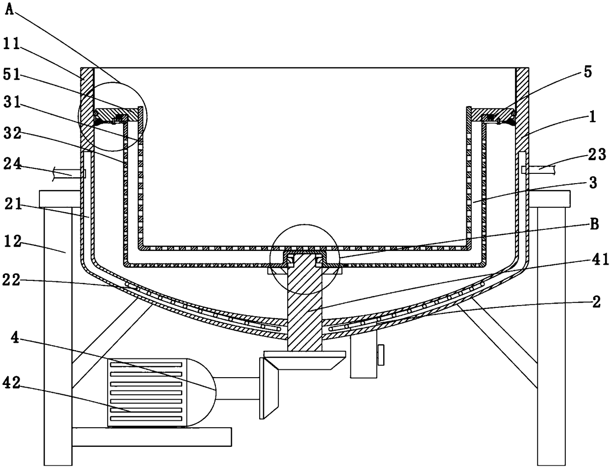
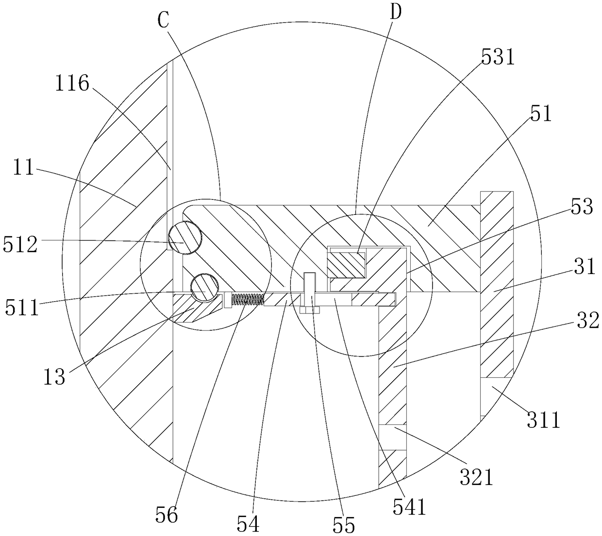
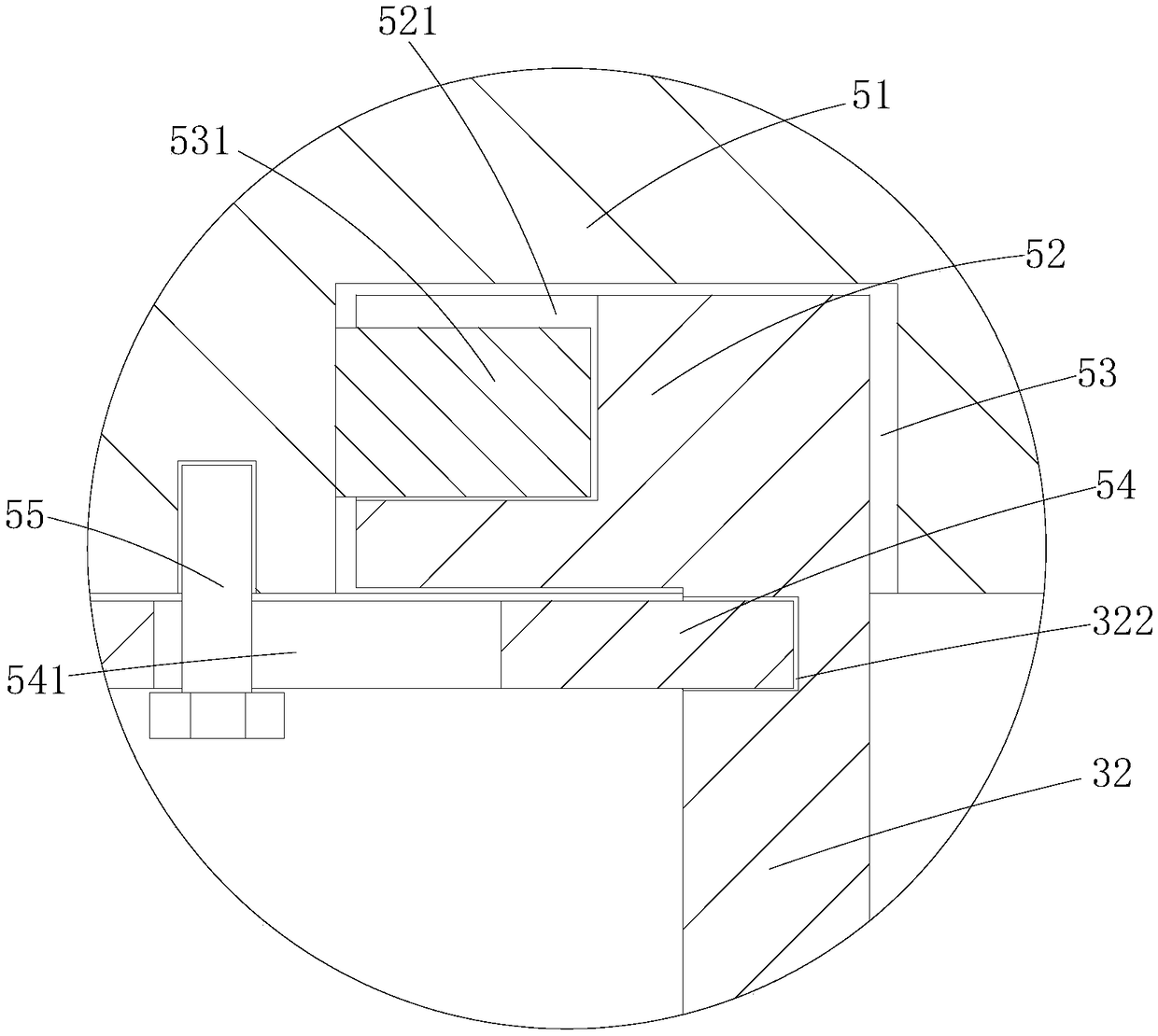
[0034] Such as Figure 1-7 As shown, a biomedical decoction device includes a reaction tank 1, a heating part 2, a liquid removal part 3 and a driving part 4, wherein the reaction tank 1 includes a tank body 11 and a bracket 12, and the tank body 11 It is a metal tank, the bracket 12 is a metal frame, and the bracket 12 is connected to the tank body 11; the heating component 2 is arranged on the tank body 11, and the heating component 2 includes a The heating chamber 21 on the upper surface and the heating element 22 arranged in the heating chamber 21, the heating element 22 is a resistance wire, the heating element 22 is arranged in the heating chamber 21, when the heating element 22 is heated , the heating element 22 can raise the temperature of the material in the tank body 11 to a specified temperature; a steam inlet pipe 23 and a steam outlet pipe 24 are communicated on the heating chamber 21, so that the steam inlet pipe 23 can flow to the heating chamber Steam is sent ...
Embodiment 2
[0041] Such as Figure 8-9 As shown, the difference between this embodiment and Embodiment 1 is that a stirring component is added to stir the material in the first filter element, specifically: the stirring component 6 includes an air inlet pipe 61, a heating element 62 and an air supply element 63 , wherein the air intake pipe 61 is an L-shaped metal pipe, the air supply part 63 is a fan, the air supply part 63 is connected with the air intake pipe 61, and the heating part 62 is a heating wire , the heating element 62 is located in the air intake pipe 61; a filter screen 64 is arranged in the air intake pipe 61, and the filter screen 64 is a metal mesh, and the filter screen 64 and the air intake pipe 61 detachable connections.
[0042] Further, the inlet pipe 61 is provided with a socket 611, the filter 64 can be inserted through the socket 611, and a sealing layer 641 is bonded on the left and right side walls of the filter 64, the sealing The layer 641 is a rubber layer...
Embodiment 3
[0044] Such as Figure 10-12 As shown, the difference between this embodiment and Embodiment 1 is that this embodiment has a discharge component, specifically: the discharge component 7 includes a discharge pipe 71, a valve 72, a cooling chamber 73, an inlet pipe 74, an outlet Liquid pipeline 75 and liquid supply pipeline 76, described discharge pipeline 71 is a metal pipeline, and described discharge pipeline 71 is connected with the bottom of described tank body 11; Rib 711, the heat dissipation rib 711 is a metal sheet; the valve 72 is a ball valve, and the valve 72 is arranged on the discharge pipeline 71; the cooling chamber 73 is located on the side wall of the discharge pipeline 71 The upper layer of cavity, the liquid inlet pipe 74 and the liquid outlet pipe 75 are all connected with the cooling chamber 73, so that the liquid inlet pipe 74 passes into the cooling chamber 73 and cold water is passed into the outlet pipe 71. The liquid medicine is cooled.
[0045] Furt...
PUM
 Abstract
Description
Claims
Application Information
 - Generate Ideas
- Intellectual Property
- Life Sciences
- Materials
- Tech Scout
- Unparalleled Data Quality
- Higher Quality Content
- 60% Fewer Hallucinations
Browse by: Latest US Patents, China's latest patents, Technical Efficacy Thesaurus, Application Domain, Technology Topic, Popular Technical Reports.
© 2025 PatSnap. All rights reserved.Legal|Privacy policy|Modern Slavery Act Transparency Statement|Sitemap|About US| Contact US: help@patsnap.com


