
Patsnap Eureka
For R&D, Patsnap Eureka makes reading and utilizing patents & technical documents easy.
Patsnap Eureka AIR
Designed for self-driven R&D workflows. Generate viable solutions, solve complex R&D challenges, empower your innovation with AI.

Patsnap Eureka Materials
Designed for material experts only. Revolutionize your material R&D, from search, analyze, to developing new materials.

TechResearch
Generate reliable direction feasibility study reports for your R&D in just a few steps.

TechSeek
Discover and master advanced knowledge NOW. Basics, ideas, possibilities, all at once.

TechMind
As an expert in R&D Theories, TechMind can generates customized viable solutions instantly.

TechRisk
Analyze your overall solution with one click, know your potential R&D risks in advance.

TechMonitor
Get weekly tech updates, stay abreast of the latest tech innovations and key insights.
A vertical building wall plant wind shielding device
A technology for buildings and walls, which is applied in the field of vertical building wall plant windshield devices, and can solve problems such as smashing facilities and hitting passers-by
- Summary
- Abstract
- Description
- Claims
- Application Information
AI Technical Summary
Problems solved by technology
Method used
Image

Examples
Embodiment 1
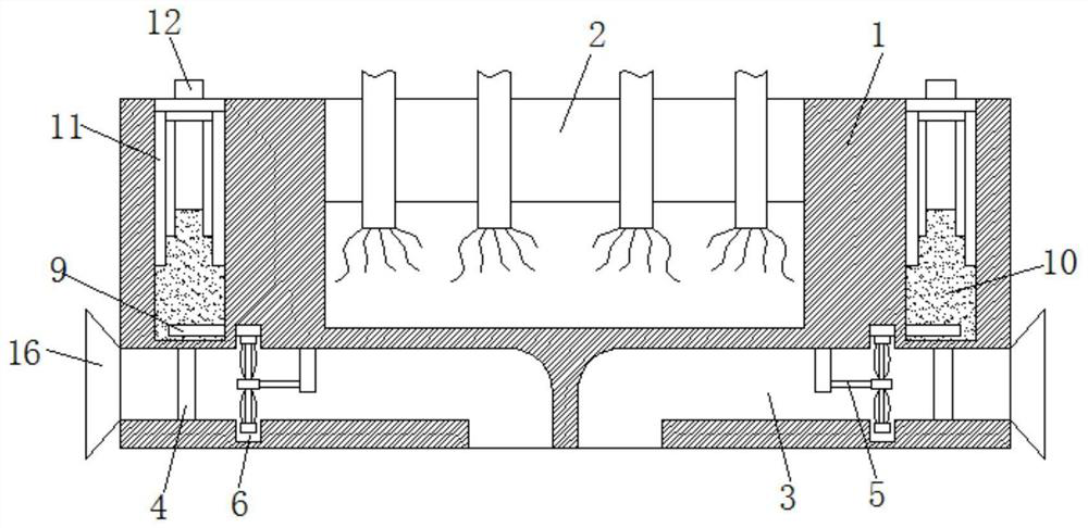
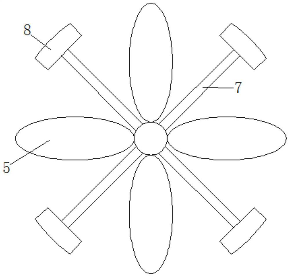
[0019] Refer Figure 1-2 A vertical building wall plant windshield, including planting platform 1, planted on planting platform 1, planting groove 2, planting plants, planting plants, all over the grown platform 1, portable 3, into the wind The channel 3 of the passage 3 is mounted having a wind pressure valve 4, and the winding air passage 3 wels the wind toward the impeller 5, and the inner wall of the in the airway 3 is located at the position of the impeller 5, and the tip of the impeller 5 is located at the annular groove. In the case, the slider 7 is fixed between the blades of the impeller 5, and the end slide of the slide rod 7 is slidably connected to the inner wall of the upper annular groove 6, and the heat conductance plate 9 is fixed, and the heat conductance plate 9 is in contact with the friction block 8. The heat conducting plate 9 is disposed within the annular groove 6, which can effectively reduce the heat of the heat in the air passage 3. Both sides of the plant...
Embodiment 2
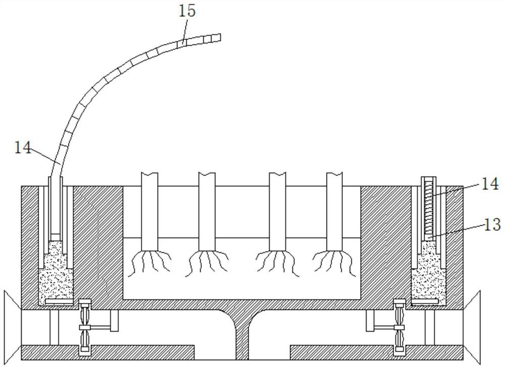
[0023] Such as image 3 In the present embodiment, the windshield 12 is provided with an apparatus passage 13, and a folding air bag 14 is fixed in the device passage 13. The lower end of the folding airbag 14 is in communication with the device chamber 10, and the outer wall expansion coefficient of the folding airbag 14 is greater than the inner wall. The expansion coefficient, and a plurality of light-transmitted holes are fabricated over the folding airbag 14, and the outer surface of the folding balloon 14 is coated with a black coating.
[0024] In this embodiment, the plant is easily sunk due to large sunlight in the summer. The summer temperature is high, the evaporation fluid is also partially evaporated, and the evaporated gas is not sufficient to abut the telescopic sleeve 11, and the evaporated gas enters the folded airbag 14 for inflation, the folding airbag 14 expansion telescopic exit device 10, due to folding airbag 14 The outer wall expansion coefficient is greater...
PUM
 Abstract
Description
Claims
Application Information
 - R&D Engineer
- R&D Manager
- IP Professional
- Industry Leading Data Capabilities
- Powerful AI technology
- Patent DNA Extraction
Browse by: Latest US Patents, China's latest patents, Technical Efficacy Thesaurus, Application Domain, Technology Topic, Popular Technical Reports.
© 2024 PatSnap. All rights reserved.Legal|Privacy policy|Modern Slavery Act Transparency Statement|Sitemap|About US| Contact US: help@patsnap.com