Judging method and system of shield machine tunneling state
A shield machine and state technology, which is applied to earth-moving drilling, mining equipment, mining equipment, etc., can solve the problem of inability to timely and accurately judge the excavation state of the shield machine, and achieve the effect of safe and efficient tunnel construction.
- Summary
- Abstract
- Description
- Claims
- Application Information
AI Technical Summary
Problems solved by technology
Method used
Image
Examples
Embodiment 1
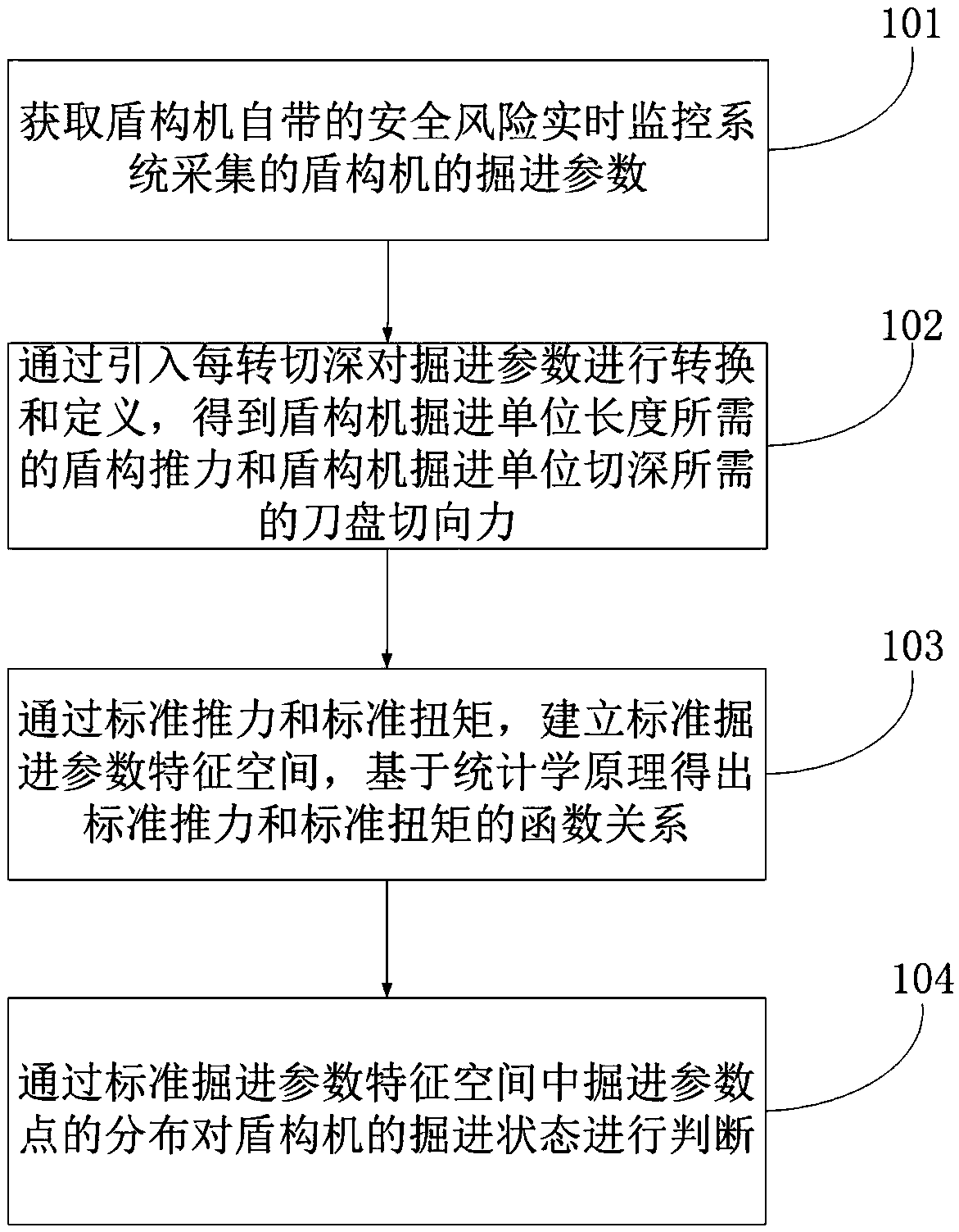
[0055] figure 1 It is a flow chart of the method for judging the tunneling state of the shield machine in Embodiment 1 of the present invention. see figure 1 , a method for judging the tunneling state of a shield machine, comprising:
[0056] Step 101, obtaining the tunneling parameters of the shield machine collected by the safety risk real-time monitoring system of the shield machine.
[0057] The tunneling parameters include: TBM thrust and cutterhead torque.
[0058] In step 102, the tunneling parameters are converted and defined by introducing the depth of cut per revolution to obtain the shield thrust required for the tunneling unit length of the shield machine and the tangential force of the cutterhead required for the tunneling unit depth of the shield machine. The shield thrust required for the tunneling unit length of the shield machine is expressed as the standard thrust
[0059] standard thrust for:
[0060]
[0061] Among them, F represents the thrust ...
Embodiment 2
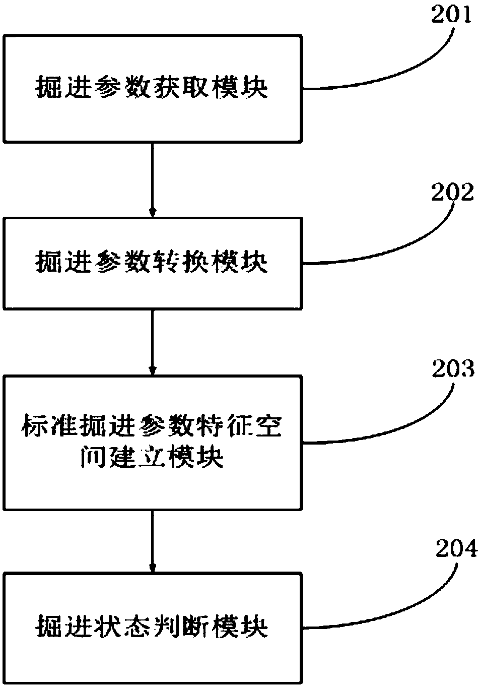
[0084] image 3 It is a system diagram for judging the tunneling state of the shield machine in Embodiment 2 of the present invention. see image 3 , a system for judging the tunneling state of a shield machine, comprising:
[0085] The excavation parameter acquisition module 201 is used to acquire the excavation parameters of the shield machine collected by the safety risk real-time monitoring system of the shield machine.
[0086] The tunneling parameter conversion module 202 is used to convert and define the tunneling parameters by introducing the depth of cut per revolution, and obtain the shield thrust required for the tunneling unit length of the shield machine and the cutter head tangential direction required for the tunneling unit depth of the shield machine force. The shield thrust required for the unit length of the excavation is expressed as the standard thrust The cutter head tangential force required for the said excavation unit depth of cut is expressed as s...
Embodiment 3
[0095] Figure 4 It is a flowchart of soil layer identification based on excavation parameters in Embodiment 3 of the present invention. see Figure 4 , this embodiment provides a method for judging the tunneling state of the shield machine according to the real-time tunneling parameters of the shield machine in a composite stratum. Specifically follow the steps below:
[0096] Step 1: Obtain the real-time excavation parameters of the shield machine through the safety risk real-time monitoring system that comes with the shield machine. The main excavation parameters collected are shield thrust, cutter head torque and depth of cut per revolution.
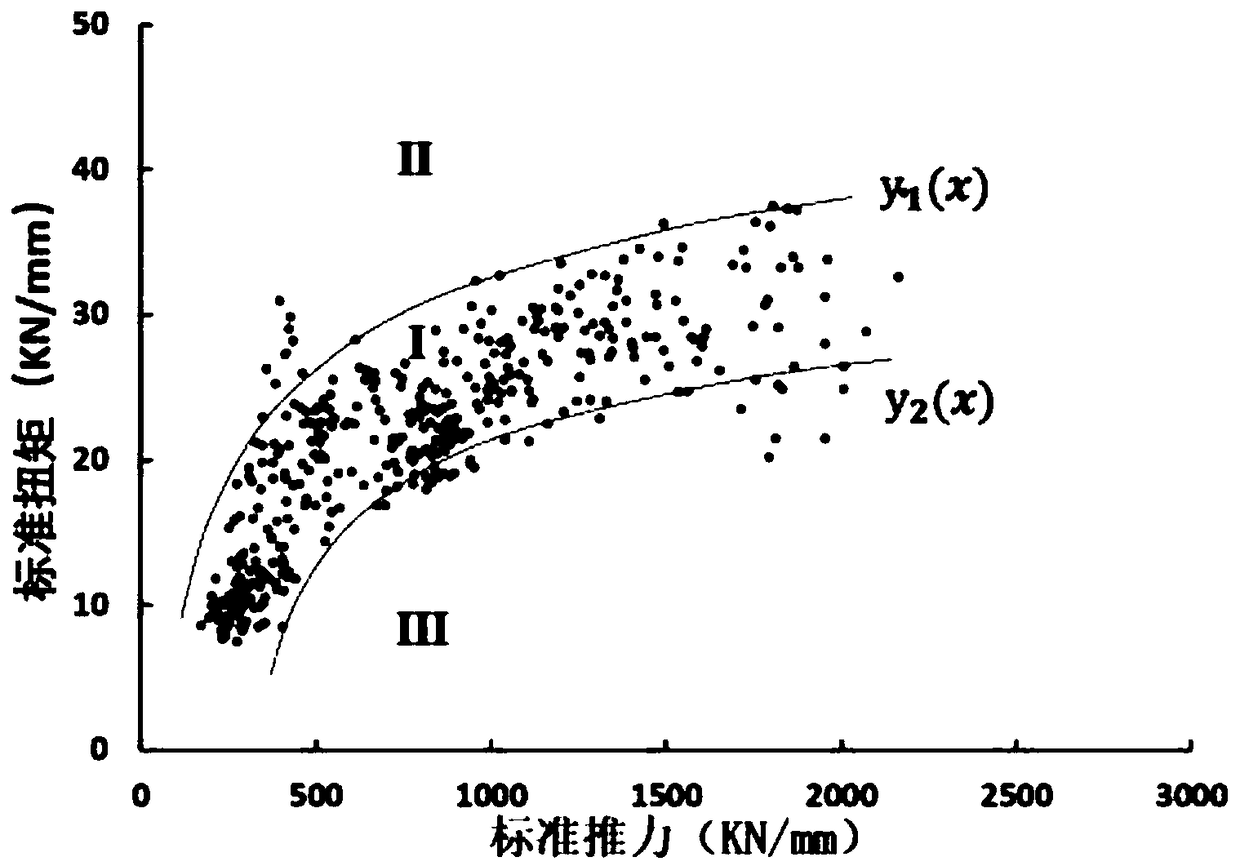
[0097] Step 2: Among the many tunneling parameters of the shield machine, many studies have shown that the thrust F of the shield machine and the torque T of the cutterhead are the most sensitive to the changes in the soil layer that the shield machine passes through and the abnormal conditions of the shield machine. Since the cha...
PUM
 Abstract
Description
Claims
Application Information
 - R&D Engineer
- R&D Manager
- IP Professional
- Industry Leading Data Capabilities
- Powerful AI technology
- Patent DNA Extraction
Browse by: Latest US Patents, China's latest patents, Technical Efficacy Thesaurus, Application Domain, Technology Topic, Popular Technical Reports.
© 2024 PatSnap. All rights reserved.Legal|Privacy policy|Modern Slavery Act Transparency Statement|Sitemap|About US| Contact US: help@patsnap.com


