
3D printing device for metal blanks with adjustable type ladder holes

A 3D printing, stepped hole technology, applied in the field of metal 3D printing, can solve the problems of reducing production efficiency, increasing production cost, inconvenient bevel connection, etc., to improve work efficiency, improve printing accuracy, and facilitate printing.

Active Publication Date: 2019-02-19
ANHUI POLYTECHNIC UNIV
View PDF5 Cites 1 Cited by
  • Summary
  • Abstract
  • Description
  • Claims
  • Application Information

AI Technical Summary

Problems solved by technology

[0005] The purpose of the present invention is to provide a metal billet 3D printing device with adjustable stepped holes, to solve the problem that the existing 3D printers proposed in the above background technology generally have a single function. When printing a metal billet with a central hole, generally The solid metal billet is first printed by the printer, and then the printed metal billet is transported to the punching machine or cutting machine to process the center hole. This requires the purchase of punching equipment or cutting equipment on the basis of the original 3D printer. Increased production cost, but also reduced production efficiency, and when the inside of the metal billet has a central hole of different sizes in a stepped shape, it is not convenient to adjust the aperture size of the central hole, and it is not convenient to adjust the inclined plane and adjacent two different sizes. The connection at the center hole will affect the printing effect of the inclined plane

Method used


Image

  • 3D printing device for metal blanks with adjustable type ladder holes
  • 3D printing device for metal blanks with adjustable type ladder holes
  • 3D printing device for metal blanks with adjustable type ladder holes

Examples


Embodiment Construction

[0022] The following will clearly and completely describe the technical solutions in the embodiments of the present invention with reference to the accompanying drawings in the embodiments of the present invention. Obviously, the described embodiments are only some, not all, embodiments of the present invention. Based on the embodiments of the present invention, all other embodiments obtained by persons of ordinary skill in the art without making creative efforts belong to the protection scope of the present invention.

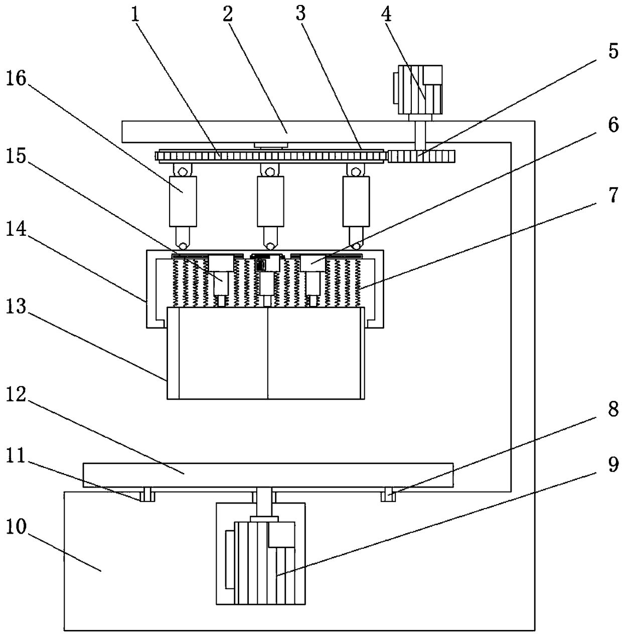
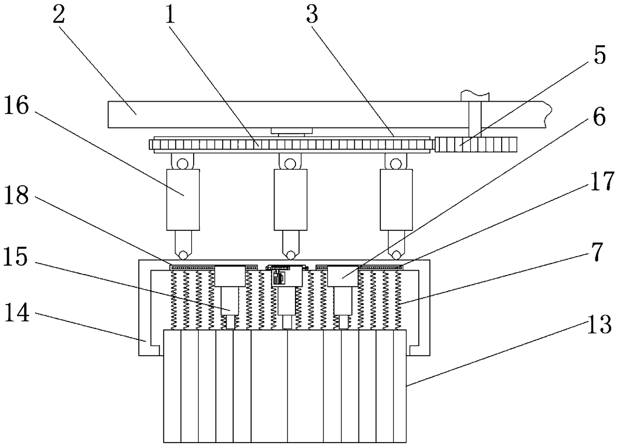
[0023] see Figure 1-6, an embodiment provided by the present invention: a metal blank 3D printing device with adjustable stepped holes, including a support frame 2, a base 10, a processing platform 12, a main template group 13 and a mounting seat 14, and the top of the base 10 is provided with Ring chute 11, the top of the base 10 is provided with a processing platform 12, the bottom of the processing platform 12 is provided with an annular slide bar 8 matche...


PUM

PropertyMeasurementUnit
thicknessaaaaaaaaaa

Abstract

The invention discloses a 3D printing device for metal blanks with adjustable type ladder holes. The 3D printing device for the metal blanks with the adjustable type ladder holes comprises a supporting frame, a base, a processing platform, a main formwork group and a mounting seat. Annular sliding grooves are formed in the top of the base, the processing platform is arranged at the top of the base, annular sliding strips matched with the annular sliding grooves are arranged at the bottom of the processing platform, a first motor is arranged in the base directly below the processing platform, the output end of the first motor is fixed to the bottom of the processing platform, and the supporting frame is arranged above the base. A plurality of secondary formwork groups on the main formwork group can be divided, the diameter of a circle formed by outermost metal formworks at the head and the tail positions differs the thickness of one metal formwork, the metal formworks at different positions can be conveniently used for being matched with the processing platform, the metal blanks provided with center holes with different hole diameters are printed, the precision of the center holes of the printed metal blanks is conveniently improved, the production cost is reduced, and the working efficiency is improved.

Description

technical field [0001] The invention relates to the technical field of metal 3D printing, in particular to a metal blank 3D printing device with adjustable stepped holes. Background technique [0002] 3D printing is a kind of rapid prototyping technology. It is based on digital model files and uses bondable materials such as molten metal (alloy), powdered metal (alloy) or plastic to construct by layer-by-layer printing. Object technology, the biggest feature of this technology is that it can create objects of almost any shape, and it has become a frontier research field both internationally and domestically. [0003] 3D printing is usually realized by using digital technology material printers. In the past, it was often used to make models in the fields of mold manufacturing and industrial design. Now it is gradually used in the direct manufacture of some products. It has been printed using this technology. The components are based on the computer three-dimensional design m...

Claims


Application Information

Patent Timeline
Patent Type & Authority Applications(China)
IPC IPC(8): B22F3/00B33Y30/00B22F12/00B22F12/30
CPCB22F3/00B33Y30/00
Inventor 王刚王振涛桂凯旋郭跃东
Owner ANHUI POLYTECHNIC UNIV
Learn More