
Horizontal stirring machine

A technology of horizontal mixer and mixing tank, which is applied in the direction of mixer accessories, mixers, mixing methods, etc., and can solve the problems of inability to realize continuous feeding, low mixing efficiency, and inability to ensure the uniformity of mixing of multi-component high-viscosity materials, etc. Achieve the effects of easy cleaning, prolonging the stirring time and preventing accumulation

Active Publication Date: 2019-02-19
重庆市智翔铺道技术工程有限公司
View PDF7 Cites 2 Cited by
  • Summary
  • Abstract
  • Description
  • Claims
  • Application Information

AI Technical Summary

Problems solved by technology

As mentioned above, although the stirring device has the stirring function and can meet the stirring of ordinary materials, it cannot Realize continuous feeding, and have the disadvantage of low stirring efficiency
In addition, multi-component high-viscosity materials are widely used in road engineering, pharmaceutical engineering and other fields. These fields require high mixing uniformity of multi-component high-viscosity materials, and as mentioned above, the stirring device cannot guarantee multi-component high-viscosity Material mixing uniformity

Method used


Image

  • Horizontal stirring machine
  • Horizontal stirring machine
  • Horizontal stirring machine

Examples


Embodiment

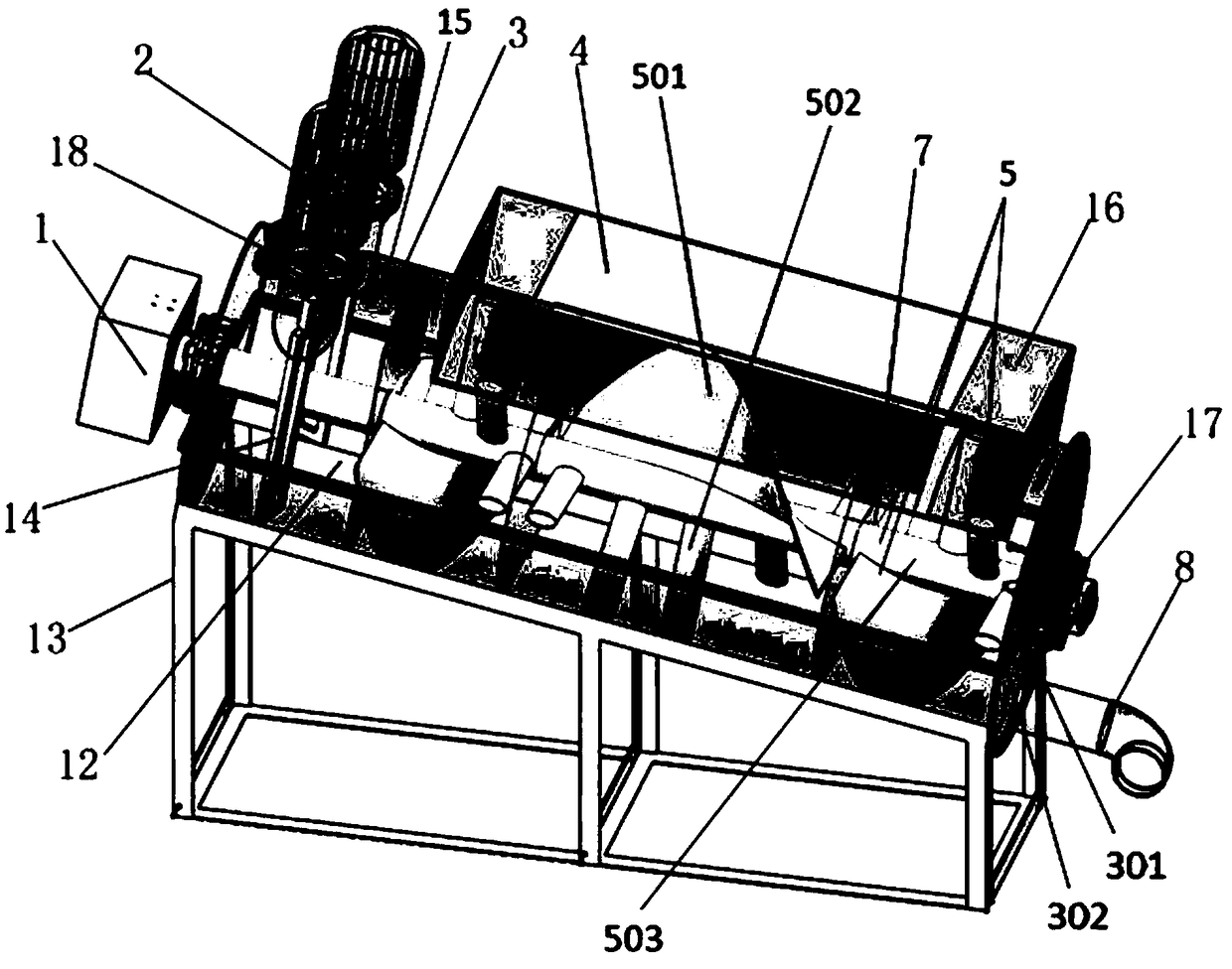
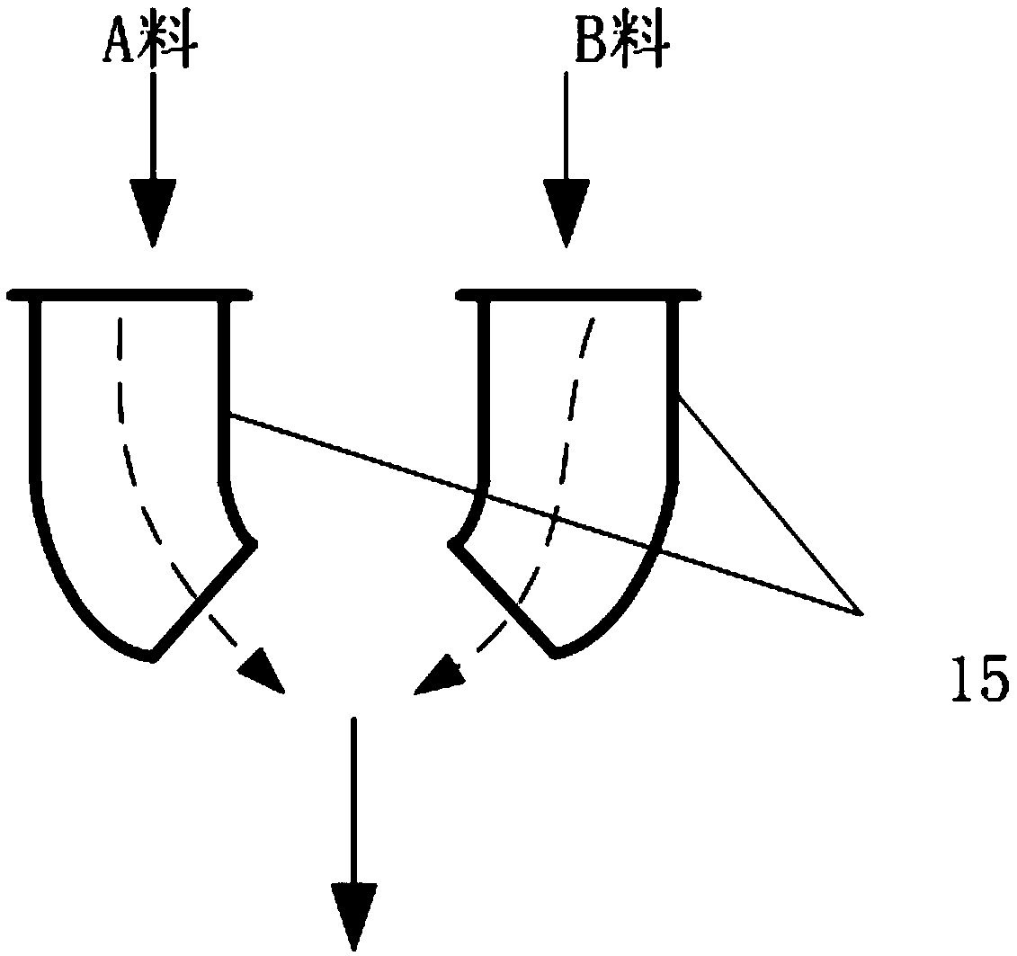
[0024] A horizontal mixer such as figure 1 As shown, a stirring tank 3 is included, an agitator 5 is arranged in the agitating tank 3, a first power system 1 for driving the agitator 5 is arranged outside the agitating tank 3, and a feed passage 15 and a discharge channel 15 are arranged on the agitator. channel 8;

[0025] Wherein, one end of the stirring tank 3 is provided with a premixing device communicated with the stirring tank 3, a buffer tank 4 communicating with the stirring tank 3 is arranged above the stirring tank 3, the stirrer 5 is axially arranged in the stirring tank 3, and the feed channel 15 Located on the premixing device, the discharge channel 8 is located at the end of the mixing tank 3 away from the premixing device;

[0026] Wherein, the mixing tank 3 is inclined, so that the end of the mixing tank 3 close to the premixing device is higher than the end of the mixing tank 3 away from the premixing device;

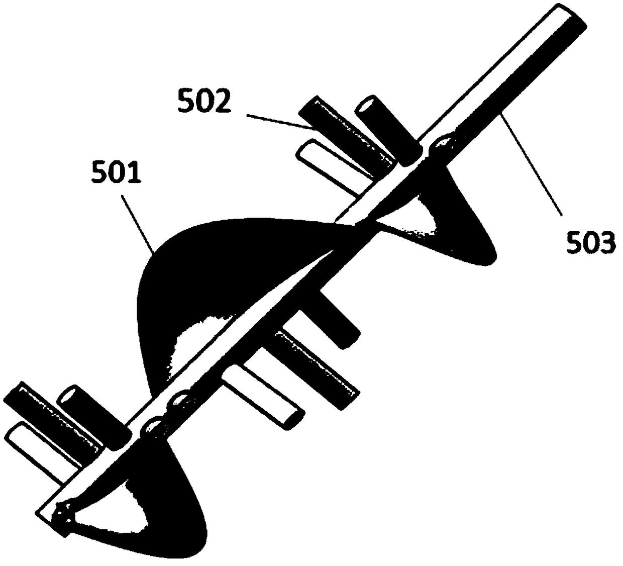
[0027] Among them, the mixer 5 such as image...


PUM


Abstract

The invention provides a horizontal stirring machine. The stirring machine comprises a stirring tank, a stirring device is arranged in the stirring tank, a first power system for driving the stirringdevice is arranged outside the stirring tank, and the stirring device is provided with a feeding channel and a discharging channel; one end of the stirring tank is provided with a premixing device communicated with the stirring tank, a buffering tank communicated with the stirring tank is arranged above the stirring tank, the stirring device is axially disposed in the stirring tank, the feeding channel is located on the premixing device, the discharging channel is located at the end, away from the premixing device, of the stirring tank, and the stirring tank is obliquely arranged; the stirringdevice includes a rotating shaft, a spiral blade disposed on the rotating shaft and a plurality of column bodies laterally disposed along a spiral path of the spiral blade at intervals. According tothe stirring machine, not only can a mixed material body be fully mixed, but also the mixed material body can be fully dispersed and stirred, and under the cooperation of technical features such as multiple stirring chambers and flow limiting holes, self-adhesion of a multi-component high-adhesion material in a stirring process is prevented, so that the problem that the multi-component high-adhesion material is stirred nonuniformly is solved.

Description

technical field [0001] The invention relates to a stirring device, in particular to a horizontal mixer for stirring multi-component (the multi-component in the invention refers to two or more than two components) high-viscosity materials. Background technique [0002] The existing stirring device is mainly composed of a stirring tank and an agitator located in the stirring tank, such as the disclosed spiral stirring device of CN202878492U, which includes a tank body, and a guide tube is fixedly arranged at the bottom of the tank body, and the guide tube includes a vane The wheel shaft is provided with multiple sets of impellers, and the upper end of the impeller shaft extending outside the guide tube also includes a fixed shaft, and a rotating shaft is placed outside the fixed shaft; another example is the cement yellow sand disclosed in CN107097345A The high-efficiency mixing device includes a shell, and sliding grooves are inlaid symmetrically on both sides of the middle p...

Claims


Application Information

Patent Timeline
Patent Type & Authority Applications(China)
IPC IPC(8): B01F13/10B01F15/02B01F15/00B01F3/10B01F23/47
CPCB01F23/47B01F33/821B01F35/00B01F35/717
Inventor 周启伟岳晓文郝增恒王民杨杰赵云陈诚吴雪柳
Owner 重庆市智翔铺道技术工程有限公司
Learn More