Camera module, terminal, terminal control method, and computer readable storage medium
A technology for terminal control and storage media, which is applied to equipment with a rotatable camera, image communication, telephone structure, etc. It can solve the problems of poor user experience and inability to achieve multi-angle shooting, and achieve the effect of improving user experience.
- Summary
- Abstract
- Description
- Claims
- Application Information
AI Technical Summary
Problems solved by technology
Method used
Image

Examples
no. 1 example
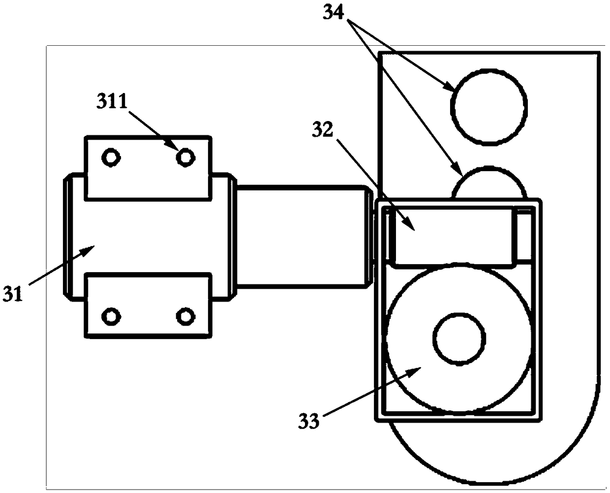
[0069] Such as image 3 As shown, the first embodiment of the present application provides a camera module, the camera module includes a stepping motor 31, a worm 32, a turbine 33 and a camera module 34;
[0070] The output shaft of the stepping motor 31 is connected to the worm 32, the worm 32 is engaged with the worm gear 33, and the worm gear 33 is fixedly connected to the camera module 34;
[0071] The stepper motor 31 is used to obtain a pulse current signal, and control the rotation of the stepper motor 31 according to the pulse current signal; the rotation of the stepper motor 31 drives the movement of the worm 32 and the turbine 33, The rotation of the camera module 34 is controlled by the movement of the worm 32 and the scroll wheel 33 .
[0072] Such as Figure 4 as shown, Figure 4 It is a structural schematic view of another viewing angle of the camera module according to the embodiment of the present application. At this time, the camera module 34 is in an init...
no. 2 example
[0083] Such as Figure 9 As shown, the second embodiment of the present application provides a terminal 40, the terminal 40 includes a stepper motor control module (not shown in the figure) and the camera module described in the first embodiment;
[0084] The stepping motor control module is used to obtain a stepping motor control signal; generate a pulse current signal according to the stepping motor control signal, and the pulse current signal is used to control the rotation of the camera module.
[0085] In this embodiment, the camera module is arranged on the side of the housing of the terminal 40, which can better realize a full screen.
[0086] Please refer to the aforementioned Figure 4 As shown, in this embodiment, the stepper motor 31 of the camera module is fixedly connected to the housing of the terminal 40 through screw holes 311 and screws.
[0087] In order to better explain the control process of the camera module, the following takes the mobile phone as an e...
no. 3 example
[0092] Such as Figure 12 As shown, the third embodiment of the present application provides a terminal control method, and the terminal may refer to the second embodiment, and details are not described here. The methods include:
[0093] Step S51 , generating a first stepper motor control signal when it is detected that the terminal enters the camera mode.
[0094] Step S52, obtain the first stepper motor control signal through the stepper motor control module of the terminal, and generate a first pulse current signal according to the first stepper motor control signal; the first pulse current signal is used It is used to control the rotation of the stepping motor of the terminal, so that the camera module of the terminal rotates to a preset angle position for shooting.
[0095] In this embodiment, the preset angle may be any angle between 0° and 180°.
[0096] In one embodiment, the stepping motor control module of the terminal acquires the first stepping motor control si...
PUM
 Abstract
Description
Claims
Application Information
 - Generate Ideas
- Intellectual Property
- Life Sciences
- Materials
- Tech Scout
- Unparalleled Data Quality
- Higher Quality Content
- 60% Fewer Hallucinations
Browse by: Latest US Patents, China's latest patents, Technical Efficacy Thesaurus, Application Domain, Technology Topic, Popular Technical Reports.
© 2025 PatSnap. All rights reserved.Legal|Privacy policy|Modern Slavery Act Transparency Statement|Sitemap|About US| Contact US: help@patsnap.com