
Mobile terminal heat dissipation structure and mobile terminal

A mobile terminal, heat dissipation structure technology, applied in the direction of telephone structure, electrical equipment structural parts, cooling/ventilation/heating transformation, etc., can solve problems such as poor heat dissipation

Inactive Publication Date: 2019-02-15
NUBIA TECHNOLOGY CO LTD
View PDF11 Cites 7 Cited by
  • Summary
  • Abstract
  • Description
  • Claims
  • Application Information

AI Technical Summary

Problems solved by technology

[0003] The main purpose of the present invention is to propose a heat dissipation structure of a mobile terminal and a mobile terminal, aiming at providing a heat dissipation structure of a mobile terminal to help the mobile terminal improve the problem of poor heat dissipation

Method used


Image

  • Mobile terminal heat dissipation structure and mobile terminal
  • Mobile terminal heat dissipation structure and mobile terminal
  • Mobile terminal heat dissipation structure and mobile terminal

Examples


Embodiment 1

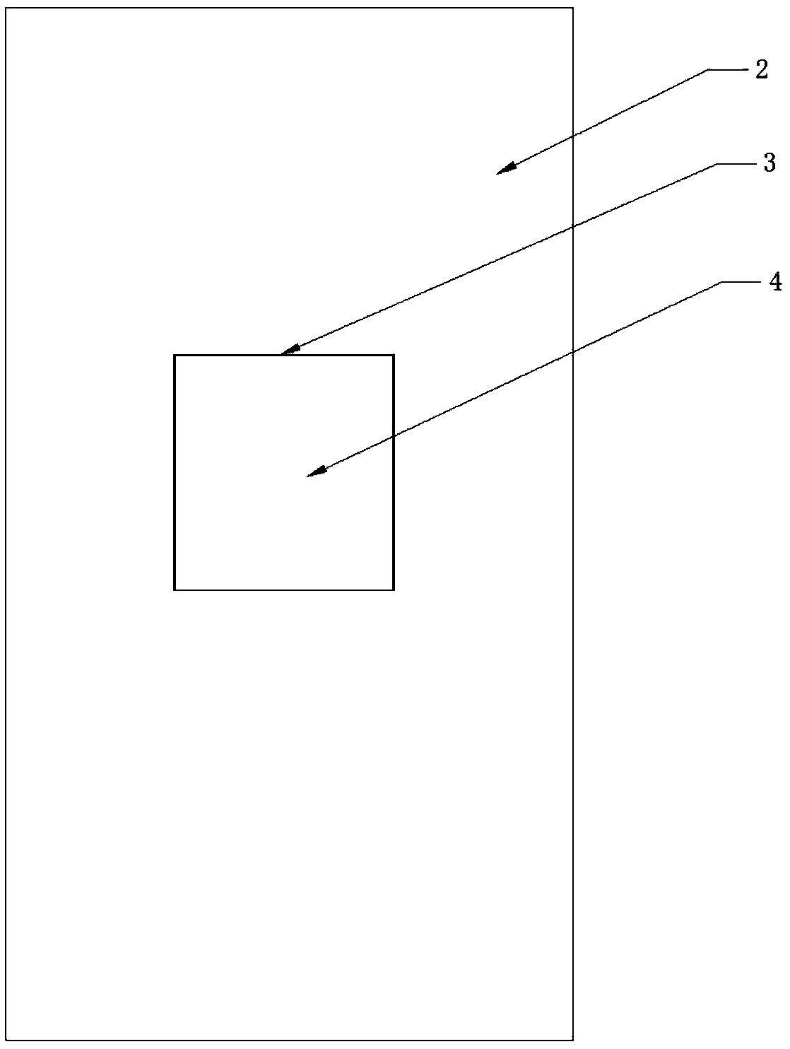
[0049] The first embodiment of the present invention provides a heat dissipation structure for a mobile terminal, such as image 3 and Figure 4 As shown, it includes a terminal body 1 and a rear cover 2, the rear cover 2 covers the rear of the terminal body 1, and the front of the terminal body 1 is the screen of the mobile terminal (not shown in the figure); in order to help move Terminal heat dissipation, the space between the terminal body and the back cover is provided with a fan for cooling the terminal body; the number of fans can be one or more, and the size of the fan is 17×17mm or 15×15mm; the The fan is turned on when the temperature of the mobile terminal is too high, and is turned off after the heat dissipation of the mobile terminal is completed; an opening 3 is arranged on the rear cover, and a cover plate 4 is arranged on the opening; preferably, the opening 3 and the cover plate 4 are square , not less than 30×30mm.

[0050]A locking assembly is provided bet...

Embodiment 2

[0061] The second embodiment of the present invention provides a mobile terminal, the mobile terminal is provided with a mobile terminal heat dissipation structure;

[0062] Such as image 3 and Figure 4 As shown, it includes a terminal body 1 and a rear cover 2, the rear cover 2 covers the rear of the terminal body 1, and the front of the terminal body 1 is the screen of the mobile terminal (not shown in the figure); in order to help move Terminal heat dissipation, the space between the terminal body and the back cover is provided with a fan for cooling the terminal body; the number of fans can be one or more, and the size of the fan is 17×17mm or 15×15mm; the The fan is turned on when the temperature of the mobile terminal is too high, and turned off after the cooling of the mobile terminal is completed. An opening 3 is provided on the rear cover, and a cover plate 4 is provided on the opening; preferably, the opening 3 and the cover plate 4 are square, not less than 30×3...


PUM


Abstract

The invention discloses a mobile terminal heat dissipation structure and a mobile terminal. The mobile terminal heat dissipation structure comprises a terminal body and a rear cover covering the rearpart of the terminal body; a fan for carrying out heat dissipation on the terminal body is arranged in a space between the terminal body and the rear cover; an opening is formed on the rear cover, anda cover board is arranged on the opening; the cover board is connected with the opening on the rear cover by at least one group of connecting pieces; when the fan is closed, the cover board and the opening on the rear cover are tightly closed under the connection of the connecting pieces; and when the fan is opened, the cover board is popped out of the opening on the rear cover, and is kept at acertain distance with the opening on the rear cover under the connection of the connecting pieces. According to the invention, the fan is utilized to carry out heat dissipation on the mobile terminal,and when the fan is opened, the cover board is popped out of the opening on the rear cover and is kept at a certain distance with the opening, so that airflow generated by the fan flows, thereby reinforcing a heat dissipation effect.

Description

technical field [0001] The present invention relates to the technical field of mobile terminals, in particular to a heat dissipation structure of a mobile terminal and the mobile terminal. Background technique [0002] At present, mobile terminals on the market adopt the design concept of natural heat dissipation system, which transfers the heat inside the mobile terminal to the screen and back cover through radiation and heat conduction, and exchanges heat with the environment through the screen and back cover, thereby controlling the surface temperature of the mobile terminal. Mobile terminals designed with a natural convection cooling system include: screen, middle frame, single board, CPU, battery, and rear cover. The heat of the CPU is finally transferred to the screen and the back cover through heat conduction, and the screen and the back cover exchange heat with the environment through radiation and natural convection. Due to the limitation of the heat dissipation sur...

Claims


Application Information

Patent Timeline
Patent Type & Authority Applications(China)
IPC IPC(8): H04M1/02H05K7/20
CPCH04M1/026H05K7/20136
Inventor 李建中
Owner NUBIA TECHNOLOGY CO LTD
Learn More