An automatic winding mechanism for automobile clutch coil forming
A coil forming and automatic online technology, applied in coil manufacturing, inductance/transformer/magnet manufacturing, electrical components, etc., can solve the problems of wasting time and low efficiency, and achieve the effect of reducing production costs, reducing labor, and saving time
- Summary
- Abstract
- Description
- Claims
- Application Information
AI Technical Summary
Problems solved by technology
Method used
Image
Examples
Embodiment 1
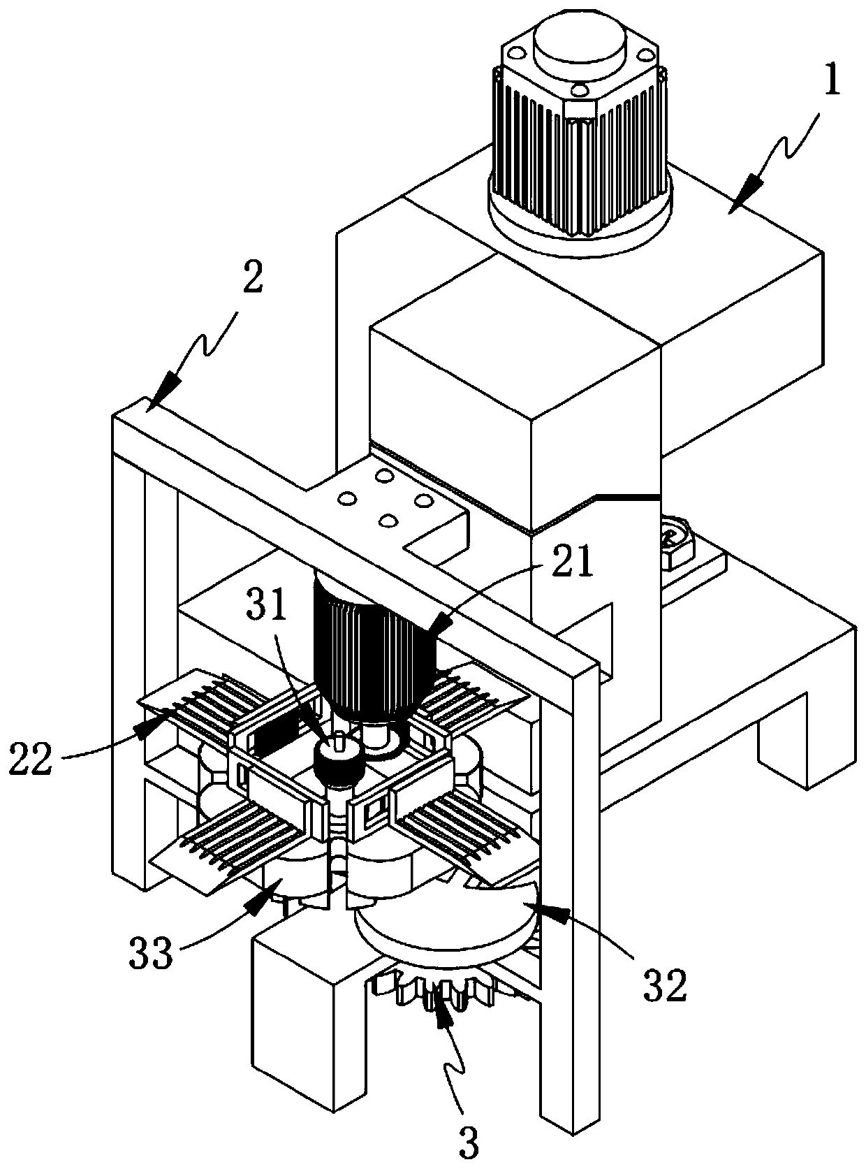
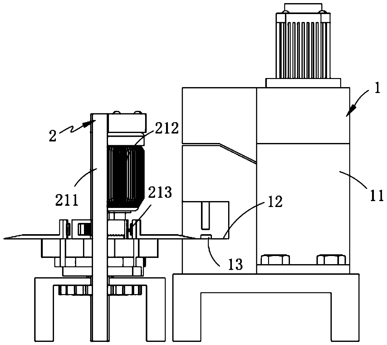
[0057] Such as figure 1 As shown, an automatic winding mechanism for automobile clutch coil forming includes:
[0058] Wiring assembly 1;
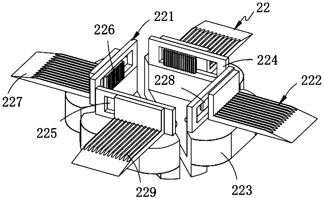
[0059] The feeding assembly 2 is arranged on one side of the wiring assembly 1 and includes a driving member 21 and a translation member 22 arranged in cooperation with the driving member 21 and slidingly arranged with the wiring assembly 1. The Several translation members 22 are arranged at equal intervals along the circumferential direction; and
[0060] Switching assembly 3, said switching assembly 3 includes a follower 31 located in the middle of a plurality of said translational members 22, a control member 32 fixedly connected to said follower 31 and mounted on said driving member 21, and a control member 32 which is rotatably arranged at all The driving member 33 on the driven member 31 and fixedly connected to the bottom end of the translation member 22, and the control member 32 is slidably arranged in the driving member 33.
[0061] In ...
Embodiment 2
[0101] Such as Figure 8 As shown, the components that are the same as or corresponding to those in the first embodiment use the reference numerals corresponding to those in the first embodiment. For the sake of simplicity, only the differences from the first embodiment are described below. The difference between the second embodiment and the first embodiment is:
[0102] Further, such as Figure 8 As shown, the driving shaft 313 and the rotating shaft 321 are both rotatably arranged on the annular holder 3212 of the frame 211 via a snap ring 3211.
[0103] It is worth mentioning that, in this embodiment, by setting the snap ring 3211 and the annular holder 3212 to cooperate and insert, on the one hand, the drive shaft 313 and the rotating shaft 321 can rotate smoothly, and on the other hand, the drive shaft 313 and the rotating shaft 321 can be rotated smoothly. The shaft 313 and the rotating shaft 321 have a supporting function.
[0104] work process:
[0105] First, manually pla...
PUM
 Abstract
Description
Claims
Application Information
 - Generate Ideas
- Intellectual Property
- Life Sciences
- Materials
- Tech Scout
- Unparalleled Data Quality
- Higher Quality Content
- 60% Fewer Hallucinations
Browse by: Latest US Patents, China's latest patents, Technical Efficacy Thesaurus, Application Domain, Technology Topic, Popular Technical Reports.
© 2025 PatSnap. All rights reserved.Legal|Privacy policy|Modern Slavery Act Transparency Statement|Sitemap|About US| Contact US: help@patsnap.com


