A Dead Zone Elimination Method for Accelerometer Injection Current Source

A technology for injecting current and accelerometers, which is applied to instruments, measuring devices, control/regulation systems, etc., and can solve problems affecting the output accuracy of accelerometers

Active Publication Date: 2021-05-07
CHINA AIR TO AIR MISSILE INST
View PDF7 Cites 0 Cited by
  • Summary
  • Abstract
  • Description
  • Claims
  • Application Information

AI Technical Summary

Problems solved by technology

[0003] The purpose of the present invention is to solve the problem that the current source that provides excitation has an output dead zone when the small current is output when the accelerometer is injected into the semi-physical simulation of the inertial navigation and guidance loop, and the output dead zone directly affects the output accuracy of the accelerometer

Method used


Image

  • A Dead Zone Elimination Method for Accelerometer Injection Current Source
  • A Dead Zone Elimination Method for Accelerometer Injection Current Source
  • A Dead Zone Elimination Method for Accelerometer Injection Current Source

Examples


Embodiment 1

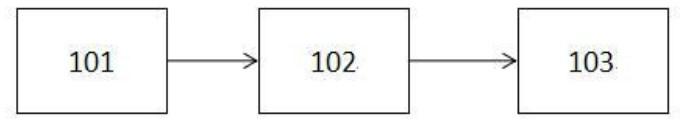
[0025] This embodiment is a method for eliminating the dead zone of an accelerometer injection current source, which is used for such as figure 1 A signal system in the shown inertial navigation and guidance circuit hardware-in-the-loop simulation platform (hereinafter referred to as the platform), in which the control signal output module 101 outputs the control signal S to the accelerometer injection current source 102, and the accelerometer injection current source 102 outputs the control signal S Under the control of S, the injection current C is output to the accelerometer 103 . The control signal S may be a digital signal, and the digital signal carries the corresponding current information that the accelerometer injection current source 102 is expected to output. The correspondence is generally linear, for example, it may be a number 8000, 9000. Correspondingly, the accelerometer injection current The source 102 outputs currents of 8 μA and 9 μA. The accelerometer inje...

Embodiment 2

[0040] The difference between this embodiment and Embodiment 1 is that, if Figure 6 As shown, this embodiment also sets an independent current source 104 connected in parallel with the accelerometer injection current source 102, the independent current source 104 obtains the control signal S from the control signal output module 101, and judges the required injection current as in the first embodiment C 0 Whether it is in the output dead zone, but the difference is that it also accepts a synchronous signal from the control signal output module 101, which enables the independent current source 104 to output the time and periodical disturbance current C 1 Current in the opposite direction C 2 , so that the actual injected current C of the accelerometer is the current C 0 , current C 1 with current C 2 Together, when the independent current source is considered to be the same high-precision current source as the accelerometer injection current source 102, the injection curre...


PUM


Abstract

The invention provides a method for eliminating the dead zone of an accelerometer injection current source, which belongs to the technical field of inertial navigation and guidance circuit hardware-in-the-loop simulation, and mainly relates to when a high-precision current source is used as the current excitation of the accelerometer, in order to improve the current injection Accuracy, how to eliminate the current source dead zone problem. In this method, when the control signal S of the accelerometer injection current source requires the accelerometer injection current source to output an injection current C within its output dead zone 0 When the injection current C 0 Superimposed on a periodic disturbance current C 1 , so that the actual output injection current C is the current C 0 with current C 1 The combined, periodic disturbance current C 1 The disturbance amplitude δ is greater than or equal to the difference between the upper limit and the lower limit of the output dead zone. The method can effectively eliminate the influence of the output dead zone of the excitation current source when the small current is output when the accelerometer is injected in the inertial navigation hardware-in-the-loop simulation, greatly improve the accuracy of the accelerometer injection, and enhance the authenticity of the simulation test.

Description

technical field [0001] The invention belongs to the technical field of semi-physical simulation of inertial navigation and guidance loops, and mainly relates to how to eliminate the problem of the dead zone of the current source in order to improve the accuracy of current injection when a high-precision current source is used as the current excitation of the accelerometer. Background technique [0002] In the hardware-in-the-loop simulation of inertial navigation and guidance loops, a high-precision current source is used as the excitation signal of the accelerometer for dynamic injection of acceleration, which has also been successfully applied in engineering; For the problem of small current output dead zone, there are usually two approaches to this problem: one is to use an expensive current source, and the output dead zone is small enough to be ignored; the other is to tolerate the existence of the dead zone and the navigation it brings error. In the existing literature...

Claims


Application Information

Patent Timeline
Patent Type & Authority Patents(China)
IPC IPC(8): G01C25/00G05B17/02
CPCG01C25/005G05B17/02
Inventor 程海彬鲁浩徐剑芸位晓峰李群生
Owner CHINA AIR TO AIR MISSILE INST
Why Eureka
Try Eureka