
Automatic telescopic clamping device capable of realizing multi-directional rotation for installation plate conveying

An automatic retractable and clamping device technology, applied in the field of tooling clamping, can solve the problems of clamping position adjustment and plugging, product quality reduction, and a large amount of dust in the adjustment position, so as to prevent rotation vibration deviation, improve work efficiency, and improve safety factor Effect

Inactive Publication Date: 2019-02-15
DONGGUAN UNIV OF TECH
View PDF1 Cites 5 Cited by
  • Summary
  • Abstract
  • Description
  • Claims
  • Application Information

AI Technical Summary

Problems solved by technology

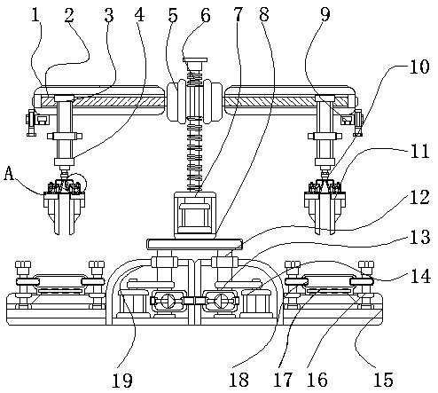
[0005] The object of the present invention is to provide a clamping device capable of multi-directional rotation and automatic expansion and contraction for mounting plate transmission, so as to solve the tool clamping on the market proposed in the above background technology. It is difficult to adjust the clamping position, and the adjustment position There is a lot of dust in the internal clamping, which causes the adjustment of the clamping position to be relatively blocked, and greatly reduces the working efficiency of the clamping equipment, and there is no certain safety distance between the processed product and the clamping equipment, which easily causes accidents in the workshop, and It is easy to cause the problem of moving the clamping equipment and reduce the quality of the product, thus easily causing serious problems of clamping damage on the product surface

Method used


Image

  • Automatic telescopic clamping device capable of realizing multi-directional rotation for installation plate conveying
  • Automatic telescopic clamping device capable of realizing multi-directional rotation for installation plate conveying
  • Automatic telescopic clamping device capable of realizing multi-directional rotation for installation plate conveying

Examples


Embodiment Construction

[0027] The following will clearly and completely describe the technical solutions in the embodiments of the present invention with reference to the accompanying drawings in the embodiments of the present invention. Obviously, the described embodiments are only some, not all, embodiments of the present invention. Based on the embodiments of the present invention, all other embodiments obtained by persons of ordinary skill in the art without making creative efforts belong to the protection scope of the present invention.

[0028] In the description of the present invention, unless otherwise stated, the meaning of "plurality" is two or more; the terms "upper", "lower", "left", "right", "inner", "outer" , "front end", "rear end", "head", "tail", etc. indicate the orientation or positional relationship based on the orientation or positional relationship shown in the drawings, and are only for the convenience of describing the present invention and simplifying the description, rather...


PUM


Abstract

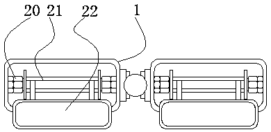
The invention relates to an automatic telescopic clamping device capable of realizing multi-directional rotation for installation plate conveying. The device comprises a top cover and a telescopic rod. A sliding groove is formed inside the top cover, and the top cover and the sliding groove are fixedly connected with each other. The left and right sides of the sliding groove are provided with a hydraulic pump, and the inside of the top cover is fixedly provided with a connecting column. The automatic telescopic clamping device capable of realizing multi-directional rotation for installation plate conveying has beneficial effects: through sliding of the hydraulic pump between the top cover and the sliding groove, the hydraulic pump and the telescopic rod can be moved left and right, and products between clamps can be moved left and right and processed; through the sliding on the sliding groove left and right, the idling clamp can be fixed at a certain position of the top cover, and it is convenient for workers to detect the products between the clamps and the top cover and safely take down the processed products; and through sliding left and right, the mobile space in the top covercan be expanded, so that the clamps are prevented from blocking taking of the products, and the safety factor of a workshop is increased.

Description

technical field [0001] The invention relates to the technical field of fixture clamping, in particular to a clamping device capable of multi-directional rotation and automatic expansion and contraction for mounting plate transmission. Background technique [0002] Tool clamping is a process device used to quickly fasten the workpiece during processing, so that the machine tool, tool, and workpiece maintain the correct relative position. That is to say, the tool fixture is an indispensable part of mechanical processing. Driven by the development of compound, intelligent and environmental protection, the fixture technology is developing towards high precision, high efficiency, modularity, combination, general purpose and economy. However, there are disadvantages in multi-directional rotation adjustment, so it is necessary to install the clamping Board transfer improvements. [0003] In China Invention Patent CN 201780004556 A-Clamping Device-Application Disclosure, it becomes...

Claims


Application Information

Patent Timeline
Patent Type & Authority Applications(China)
IPC IPC(8): B65G47/90
CPCB65G47/902
Inventor 肖力林朝阳
Owner DONGGUAN UNIV OF TECH
Learn More