Actuating unit for a process valve and process valve

A process valve, a separate technology, applied in the direction of engine components, fluid pressure actuation devices, fluid pressure actuation system safety, etc., can solve problems such as high expenditure of actuation units

Active Publication Date: 2019-02-12
BURKERT WERKE
View PDF6 Cites 0 Cited by
  • Summary
  • Abstract
  • Description
  • Claims
  • Application Information

AI Technical Summary

Problems solved by technology

[0007] This multitude of variants leads to high outlay in the manufacture of the process valve and the associated actuation unit

Method used


Image

  • Actuating unit for a process valve and process valve
  • Actuating unit for a process valve and process valve
  • Actuating unit for a process valve and process valve

Examples


Embodiment Construction

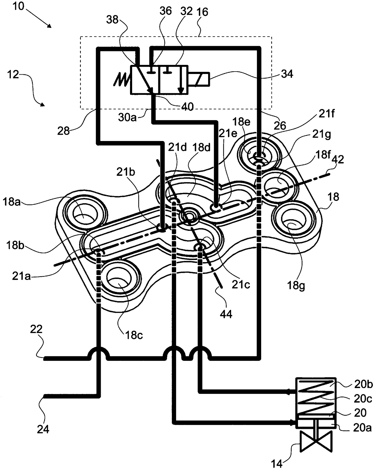
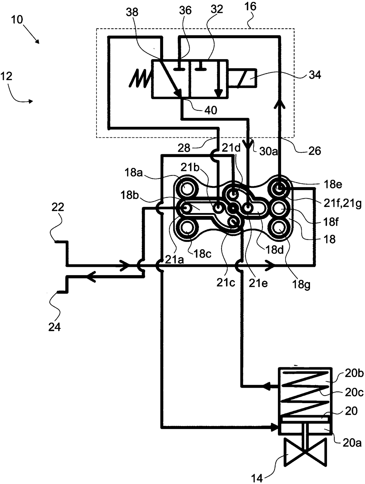
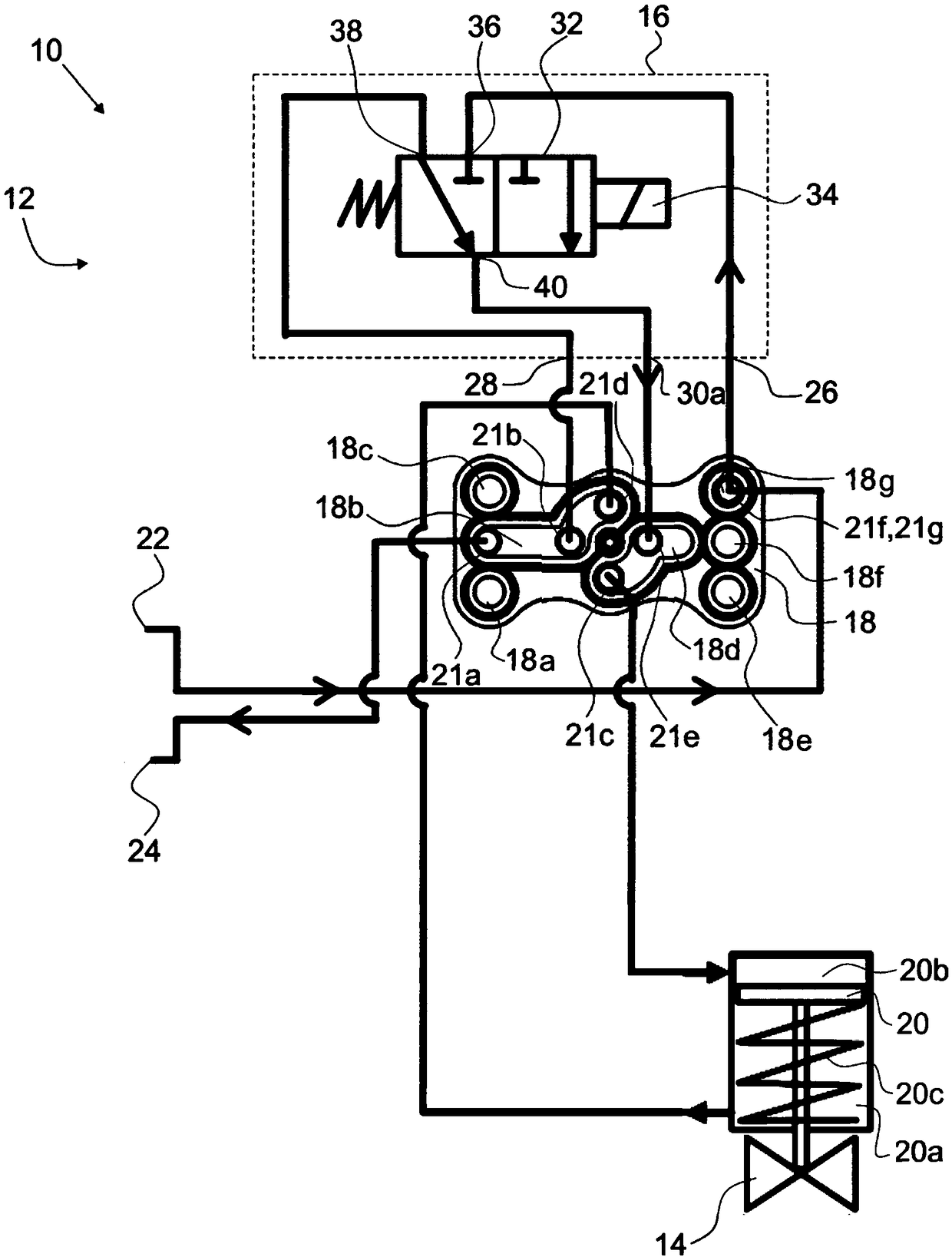
[0067] figure 1 with figure 2 A process valve 10 is shown which comprises an actuation unit 12 according to the first embodiment and a valve unit 14 which is indicated only symbolically. The actuation unit 12 may also be referred to as a pilot unit of the valve unit 14 .

[0068] The actuating unit 12 comprises a pilot valve unit 16, a separate removable seal 18 and a piston 20 configured for regulating the process valve 10, more precisely the valve unit 14, and is connected to the first pressure chamber 20a adjoins the second pressure chamber 20b.

[0069] The two pressure chambers 20a, 20b are arranged on opposite sides of the piston 20 and are preferably arranged in a cylinder, not referred to in detail, in which the piston 20 is also guided.

[0070] Furthermore, an elastic element 20c is arranged in the second pressure chamber 20b and is a spring in the illustrated embodiment. The elastic element 20c pushes the piston 20 in the direction of an end position correspond...


PUM


Abstract

An actuating unit 12 for a process valve 10 is described, which comprises a pilot valve unit 16, a separate removable seal 18 arranged between two parts through which a fluid can flow, and a piston 20configured for the adjustment of the process valve 10. The seal 18 has through openings (18a-18g) for the passage of fluid, and the adjacent parts have holes (21a-21h), such that different holes (21a-21h) are in fluid communication with each other via the through openings (18a-18g) or are fluidically separated due to an intermediate wall portion of the seal 18 depending on the fitting position ofthe seal 18. A process valve 10 having such an actuating unit 12 is furthermore described.

Description

technical field [0001] The invention relates to an actuation unit for a process valve and to a process valve with the actuation unit. Background technique [0002] Such actuating units and process valves are known in the prior art and are available on the market in various variants. [0003] On the one hand, the variety of variants results from the use of actuation units for process valves and process valves in a wide range of applications with different requirements. Furthermore, actuating units and process valves with different properties are required in certain fields of application. [0004] Process valves which close without a control signal (so-called “normally closed” valves, abbreviated: NC valves) may be required, for example, within applications. Process valves that open without a control signal (so-called "normally open" valves, abbreviated as NO valves) may additionally be required in the same application. The control signal is in particular an electrical or p...

Claims


Application Information

Patent Timeline
IPC IPC(8): F15B13/02
CPCF15B13/021F15B2013/006F15B2013/041F15B13/0401F15B20/001F16K11/07
Inventor 扬·韦斯特曼
Owner BURKERT WERKE
Why Eureka
Try Eureka