Smart tool cart and execution method
A tool cart, intelligent technology, applied in the direction of manufacturing tools, workshop equipment, instruments, etc., can solve the problems of manually finding the required tools, and achieve the effect of avoiding forgetting to return tools and misplacing them, convenient management of tools, and convenient and quick use
- Summary
- Abstract
- Description
- Claims
- Application Information
AI Technical Summary
Problems solved by technology
Method used
Image
Examples
Embodiment 1
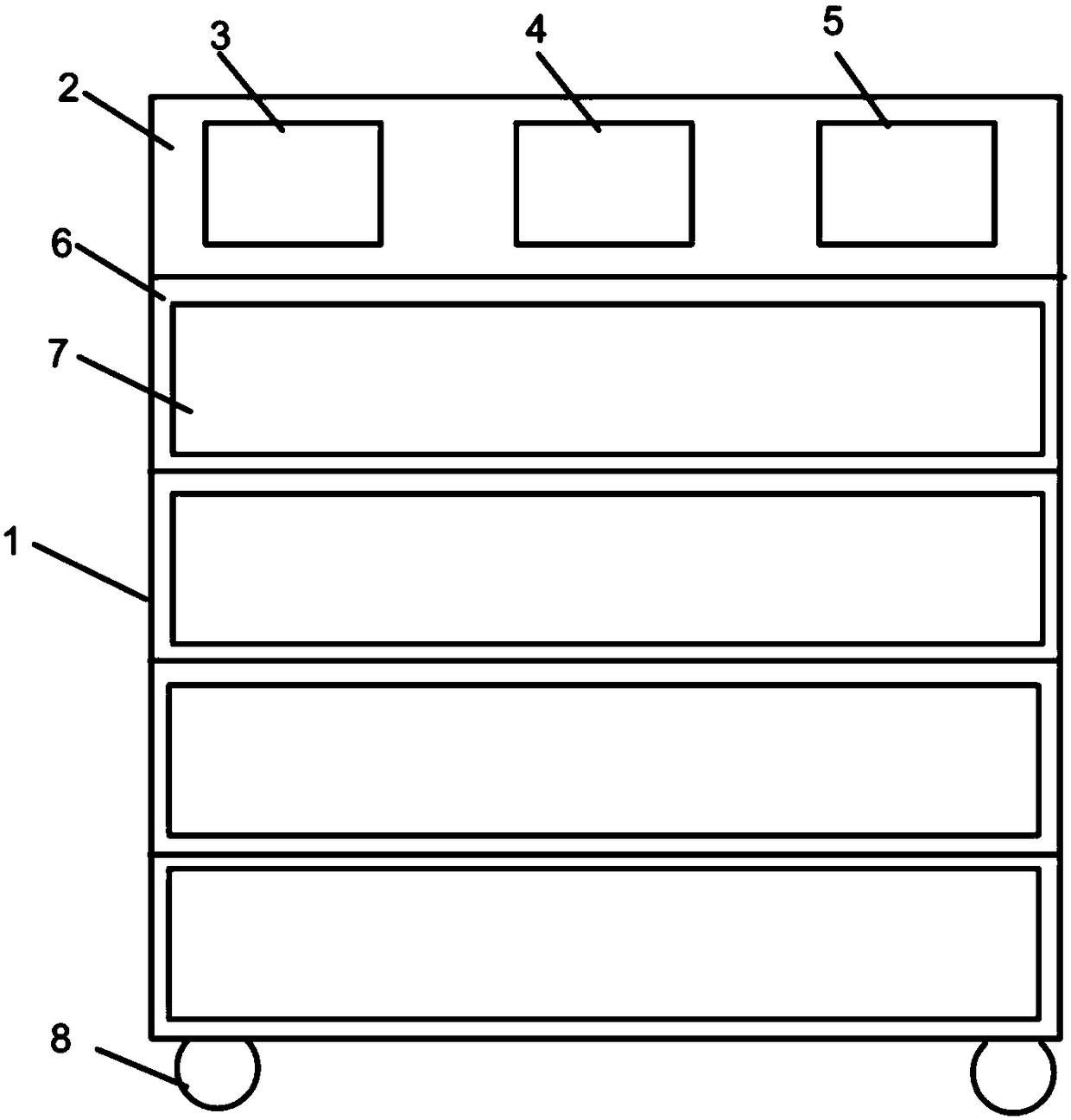
[0060] Such as figure 2 As shown, a smart tool cart is composed of a housing 1, a smart device 3, a drawer 7, a power assembly and a battery 5, wherein a first partition (not marked in the figure) divides the interior of the housing 1 into an upper Interlayer 2, a plurality of second partitions (not marked in the figure) divide the space below the upper interlayer 2 into a plurality of lower interlayers 6, and the rear interlayer (not marked in the figure) is located behind the lower interlayer 6, And communicate with the lower interlayer 6. The smart device 3 is installed inside the upper interlayer 2, the drawer 7 is installed inside the lower interlayer 6, and a plurality of power components are installed on the rear interlayer and connected with the drawer 7, so The storage battery 5 is located in the upper interlayer 2 and connected with the smart device 3 . Wherein, the smart device 3 is connected with the power assembly, so that the drawer 7 is automatically opened a...
Embodiment 2
[0070] Such as figure 2 As shown, this embodiment is a new design added on the basis of implementation 1. Optionally, it also includes a three-dimensional scanner 4 installed on the upper interlayer 2 and connected to the smart device 3 and the battery 5, It is used to send the scanned picture to the smart device 3 .
[0071] The shape of the tool is scanned by the three-dimensional scanner 4, and the image information is transmitted to the smart device 3, and when the data matching the image information is found in the database of the smart device 3, a signal is given to the power assembly The drawer 7 is caused to open and close automatically.
[0072] In this embodiment, optionally, the three-dimensional scanner 4 is fixed to the upper interlayer 2 by screws. Further, the three-dimensional scanner 4 is an existing three-dimensional scanner, and various models can be used.
Embodiment 3
[0074] Such as figure 1 As shown, this embodiment is a new design added on the basis of implementation 1. Optionally, the door frame of the housing 1 is equipped with a door 9 through a hinge, and is locked by an intelligent lock 10. The intelligent lock 10 is a mechanical Password lock or fingerprint lock or face recognition lock for extra security. A plurality of universal wheels 8 are installed on the bottom of the housing 1, which is convenient and quick to move.
PUM
 Abstract
Description
Claims
Application Information
 - R&D Engineer
- R&D Manager
- IP Professional
- Industry Leading Data Capabilities
- Powerful AI technology
- Patent DNA Extraction
Browse by: Latest US Patents, China's latest patents, Technical Efficacy Thesaurus, Application Domain, Technology Topic, Popular Technical Reports.
© 2024 PatSnap. All rights reserved.Legal|Privacy policy|Modern Slavery Act Transparency Statement|Sitemap|About US| Contact US: help@patsnap.com


