
Dust removal device for steelmaking converter sludge

A technology for a dust removal device and a steelmaking converter, which is applied in the use of liquid separation agents, dispersed particle separation, chemical instruments and methods, etc., can solve the adverse effects of production and environmental protection control, poor dust removal effect, and large dust content in flue gas, etc. To reduce environmental risks and production impacts, reduce dust content, and ensure the quality of dust removal

Inactive Publication Date: 2019-02-12
PANZHIHUA GANGCHENG GROUP
View PDF4 Cites 0 Cited by
  • Summary
  • Abstract
  • Description
  • Claims
  • Application Information

AI Technical Summary

Problems solved by technology

In the whole sludge baking process, the sludge is not dried frequently, and the flue gas emission exceeds the target value, which has brought great adverse effects on production and environmental protection control
[0003] The main reason why the sludge is not baked dry: the flue gas has a large dust content, and the dusty water after water spraying is deposited on the dehydration facility on the top of the dust collector, which reduces the cross-sectional area of ​​the dehydration partition and greatly increases the resistance loss, which reduces the suction capacity of the furnace outlet of the sludge drying furnace, reduces the utilization efficiency of heat energy, and causes the sludge to dry
[0004] The main reason causing the flue gas emission to exceed the target value is that the water hole of the spiral nozzle with a diameter of DN20 installed inside the dust collector is too small, and it is installed vertically downward on the top of the dust collector. Scale clogs the nozzle, the dust removal effect becomes poor, and the smoke emission exceeds the target value
[0005] If the sludge is not baked dry, and the smoke emission exceeds the target value, the production must be stopped immediately for maintenance and cleaning, resulting in unplanned production shutdown, which seriously affects the smooth production and brings high risks to environmental protection work.

Method used


Image

  • Dust removal device for steelmaking converter sludge

Examples


Embodiment Construction

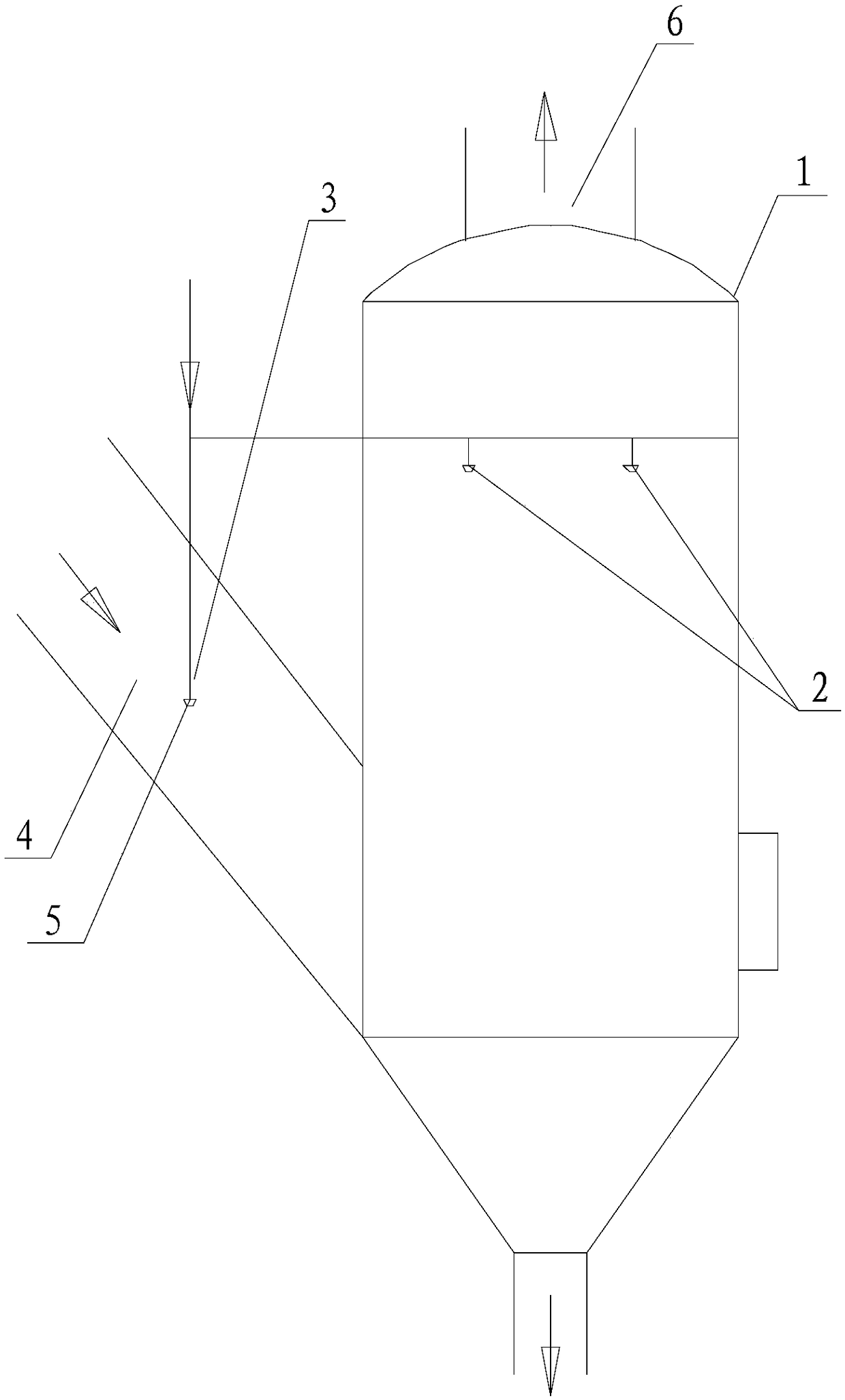
[0016] Such as figure 1 Shown is a dust removal device for steelmaking converter sludge provided by the present invention, which has low operating cost, simple structure, and can reduce environmental risks and production impacts. The dust removal device includes a dust removal tower 1 and a water spray nozzle 2, and the water nozzle 2 is arranged in the middle and upper part of the inner chamber of the dust removal tower with the outlet facing downward, and the dust removal device also includes a pre-dust removal component outside the tower 3. The flue gas that needs to be dedusted before entering the dedusting tower 1 passes through the pre-dust dedusting assembly 3 outside the tower and sprays water for pre-dedusting. In this application, the pre-dust removal component outside the tower is added, and the flue gas that needs to be dedusted before entering the dust removal tower passes through the pre-dust reduction component outside the tower to spray water for pre-dust reduc...


PUM


Abstract

The invention discloses a dust removal device, particularly discloses a dust removal device for steelmaking converter sludge, and belongs to the technical field of design and manufacture of environment protection dust removal equipment. According to the dust removal device for steelmaking converter sludge, low operation cost and simple structure are achieved, and environmental protection risks andproduction influence can be reduced. The dust removal device comprises a dust removal tower and a water spray nozzle, wherein a spray outlet of the water spray nozzle is downwards arranged on the middle upper part of an inner cavity of the dust removal tower; the dust removal device further comprises an external pre-dust-fall assembly, and flue gas needing dust removal before entering the dust removal tower sprays water through the external pre-dust-fall assembly to perform pre-dust-fall.

Description

technical field [0001] The invention relates to a dust removal device, in particular to a dust removal device for steelmaking converter sludge, and belongs to the technical field of design and manufacture of environmental protection dust removal equipment. Background technique [0002] The sludge baking flue gas purification and dust removal device is a dust removal device after the steelmaking converter sludge gas drying device. Its function is to purify the dusty flue gas generated in the baking device and then discharge it. Back to the mud pool, dehydration, purification and utilization. In the whole sludge baking process, the sludge is not dried frequently, and the flue gas emission exceeds the target value, which has brought great adverse effects on production and environmental protection control. [0003] The main reason why the sludge is not baked dry: the flue gas has a large dust content, and the dusty water after water spraying is deposited on the dehydration faci...

Claims


Application Information

Patent Timeline
Patent Type & Authority Applications(China)
IPC IPC(8): B01D47/06
CPCB01D47/06
Inventor 赖先节
Owner PANZHIHUA GANGCHENG GROUP
Learn More