
Vehicle rack-and-pinion mechanism

A technology of rack and pinion and gear teeth, which is applied in the field of rack and pinion mechanisms for vehicles, can solve problems such as deformation of the steering rack shaft, and achieve the effect of improving strength and suppressing weight increase

Inactive Publication Date: 2019-02-05
HONDA MOTOR CO LTD
View PDF12 Cites 0 Cited by
  • Summary
  • Abstract
  • Description
  • Claims
  • Application Information

AI Technical Summary

Problems solved by technology

When hardening the entire steering rack shaft, deformation may occur and the steering rack shaft may bend into a bow shape

Method used


Image

  • Vehicle rack-and-pinion mechanism
  • Vehicle rack-and-pinion mechanism
  • Vehicle rack-and-pinion mechanism

Examples


Embodiment Construction

[0028] One embodiment of the present invention will be described in detail with reference to appropriate drawings. The same reference numerals are assigned to the same constituent elements, and overlapping descriptions are omitted.

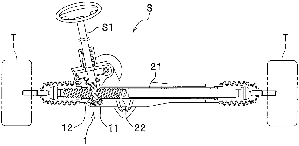
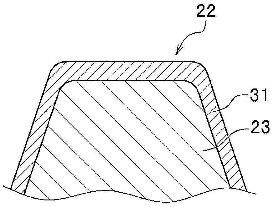
[0029] Such as figure 1 As shown, the rack-and-pinion mechanism 1 for a vehicle according to this embodiment includes a pinion gear 11 provided with pinion teeth 12 and rotatably supported around an axis, and a pinion gear 11 provided with rack teeth 22 capable of meshing with the pinion teeth 12 . Bar axis 21. In addition, the rack-and-pinion mechanism 1 for a vehicle according to this embodiment constitutes a steering device S for a vehicle.

[0030] That is, the pinion gear 11 constitutes a steering shaft S1, and rotates about its axis in conjunction with a steering operation. Then, when the pinion gear 11 rotates, the engaged rack teeth 22 slide to change the steering angle of the tire T. As shown in FIG.

[0031] In such a steering device...


PUM

PropertyMeasurementUnit
Vickers hardnessaaaaaaaaaa

Abstract

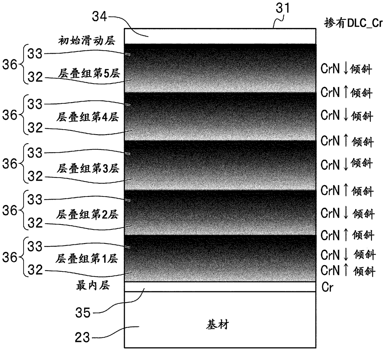
A vehicle rack-and-pinion mechanism (1) which can be applied to a steering device (S) is provided with a pinion (11) that comprises gear teeth (12) and is supported so as to be rotatable about its axis and a rack shaft (21) that comprises rack teeth (22) capable of meshing with the gear teeth (12). A coating (31) comprising a plurality of laminated films having different degrees of hardness is formed on the surface of the rack teeth (22) of the vehicle rack-and-pinion mechanism (1).

Description

technical field [0001] The present invention relates to a vehicle rack and pinion mechanism used in a steering device of an automobile or the like. Background technique [0002] Conventionally, heat treatment such as quenching is performed on racks constituting steering gears of automobiles to improve rigidity, toughness, and strength. [0003] For example, Patent Document 1 proposes induction hardening of rack teeth formed on a steering rack shaft. When the entire steering rack shaft is quenched, deformation may occur and the steering rack shaft may bend into a bow shape. However, by induction hardening only the rack teeth, it is possible to suppress bending of the steering shaft and increase the strength of the rack teeth. [0004] prior art literature [0005] patent documents [0006] Patent Document 1: Japanese Patent Application Laid-Open No. 6-264147 Contents of the invention [0007] However, in the case of the technique of increasing the strength of the rack ...

Claims


Application Information

Patent Timeline
Patent Type & Authority Applications(China)
IPC IPC(8): B62D3/12C23C14/06F16H55/26
CPCB62D3/126C23C14/0641C23C14/0611C23C28/34C23C28/322C23C28/42C23C28/36C23C28/343F16H55/26F16H57/041C23C14/06C23C14/0605F16H19/04F16H55/06
Inventor 佐藤真人
Owner HONDA MOTOR CO LTD
Learn More