
A radio frequency circuit and wireless communication device

A radio frequency circuit and radio frequency signal technology, applied in the field of communication, can solve the problem of high PA performance requirements

Active Publication Date: 2020-06-26
VIVO MOBILE COMM CO LTD
View PDF7 Cites 0 Cited by
  • Summary
  • Abstract
  • Description
  • Claims
  • Application Information

AI Technical Summary

Problems solved by technology

[0004] The embodiment of the present invention provides a radio frequency circuit and a wireless communication device, which are used to solve the problem of high performance requirements of the PA when outputting wide bandwidth and high power radio frequency signals

Method used


Image

  • A radio frequency circuit and wireless communication device
  • A radio frequency circuit and wireless communication device
  • A radio frequency circuit and wireless communication device

Examples


Embodiment 1

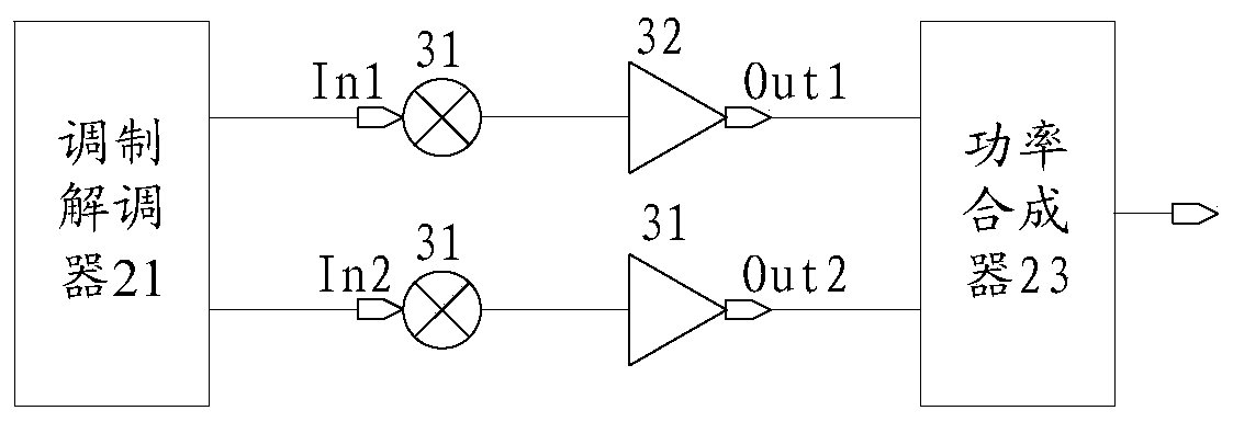
[0032] An embodiment of the present invention provides a radio frequency circuit, specifically, refer to figure 2 The radio frequency circuit shown includes: a modem 21 (Modem), N amplification paths ( figure 2 Take N=2, and the N amplification paths are respectively 221 and 222 as an example) and the power synthesizer 23 (Power Synthesis).

[0033] The input end of each amplification path in the N amplification paths (the input end of the amplification path 221 is In1, the input end of the amplification path 222 is In2) is electrically connected to the modem 21, and among the N amplification paths The output ends of each amplification path (the input end of the amplification path 221 is Out1, and the input end of the amplification path 222 is Out2) are electrically connected to the power combiner 23.

[0034] It should be noted, figure 2 N=2 is taken as an example, but the embodiment of the present invention is not limited thereto. On the basis of the above embodiments, ...


PUM


Abstract

The embodiment of the invention provides a radio frequency circuit and a wireless communication device, and relates to the technical field of communication. The device is used for solving a problem ofhigh requirement on performance of a PA when wide-bandwidth and high-power radio frequency signals are output. The circuit comprises a modem, N amplification paths and a power combiner; when bandwidth of a to-be-transmitted radio frequency signal is greater than or equal to a bandwidth threshold value and power of the to-be-transmitted radio frequency signal is greater than or equal to a power threshold value, the modem generates N modulation signals; each amplification path performs frequency mixing for one modulation signal to generate a high-frequency signal, and outputs the high-frequencysignal after power amplification; the power combiner is used for performing power combination for N high-frequency signals to generate the to-be-transmitted radio frequency signal, collection of bandwidth of the N high-frequency signals is equal to the bandwidth of the to-be-transmitted radio frequency signal, and bandwidth of the high-frequency signal generated through frequency mixing by any amplification path is less than bandwidth of the to-be-transmitted radio frequency signal; and the N is an integer greater than or equal to 2. The radio frequency circuit and the wireless communicationdevice provided by the embodiment of the invention are used for outputting of the radio frequency signals.

Description

technical field [0001] The invention relates to the technical field of communication, in particular to a radio frequency circuit and a wireless communication device. Background technique [0002] With the development of mobile terminals, the bandwidth of transmitted signals is getting wider and wider, and the power of transmitted signals is also increasing. For example, the Long Time Evolution (Long Time Evolution, The maximum bandwidth of one carrier unit (Carrier Cell, CC) in LTE is 20MHz, and in the carrier aggregation (Carrier Aggregation, CA) mode, a maximum of 5 CCs are supported, so the maximum transmission bandwidth of uplink in-band CA is 100MHz. In the era of Fifth Generation Mobile Communication Technology (5G), within the frequency range 1:450MHz~6GHz (Frequency Range 1, FR1), the maximum bandwidth of 1 CC is 100MHz, and in CA mode, it supports a maximum of 4 CCs. The bandwidth is 400MHz, and the maximum bandwidth of one CC in the frequency range 2:24.25GHz~52.6...

Claims


Application Information

Patent Timeline
Patent Type & Authority Patents(China)
IPC IPC(8): H04B1/40H04B1/00
CPCH04B1/40
Inventor 熊军
Owner VIVO MOBILE COMM CO LTD
Learn More