Current limiting circuit and current limiting method

A current-limiting circuit and current-limiting method technology, applied to circuit devices, emergency protection circuit devices for limiting overcurrent/overvoltage, emergency protection circuit devices, etc., can solve the problem of adding a charge pump circuit and slow response speed of current limiting , large peak current and other issues

Active Publication Date: 2020-02-28
ACTIONS ZHUHAI TECH CO
View PDF10 Cites 0 Cited by
  • Summary
  • Abstract
  • Description
  • Claims
  • Application Information

AI Technical Summary

Problems solved by technology

However, in the existing power distribution switch circuit with current limiting function, the current limiting response speed is very slow when the device is short-circuited instantaneously, so that there will be a large peak current at the moment of short-circuit, which may cause potential damage to the switching regulator. risk
Although the Chinese patent application whose publication number is CN102769281A discloses a fast response current limiting protection circuit, it needs to increase the charge pump circuit, which is not conducive to the realization in the low-voltage standard CMOS process.

Method used


Image

  • Current limiting circuit and current limiting method
  • Current limiting circuit and current limiting method
  • Current limiting circuit and current limiting method

Examples


Embodiment Construction

[0043] Specific embodiments of the present disclosure will be described in detail below in conjunction with the accompanying drawings. It should be understood that the specific embodiments described here are only used to illustrate and explain the present disclosure, and are not intended to limit the present disclosure.

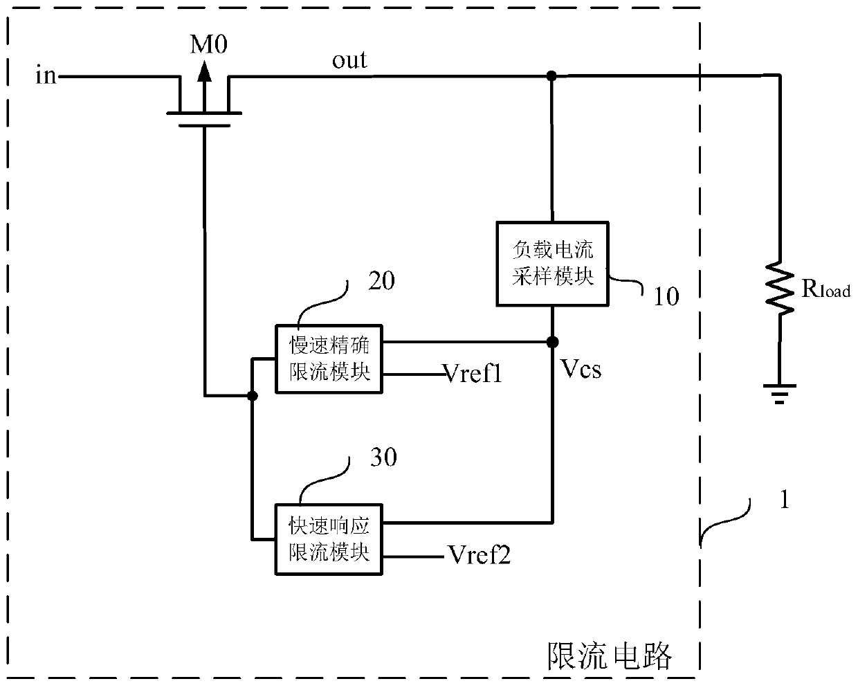
[0044] According to an embodiment of the present disclosure, a current limiting circuit 1 is provided, such as figure 1 As shown, the current limiting circuit 1 includes a load current sampling module 10, a slow and accurate current limiting module 20, a fast response current limiting module 30, and a power switch tube M0, wherein:

[0045]The load current sampling module 10 is configured to sample the load current of the power switch M0, convert the sampled load current into a voltage Vcs, and input the converted voltage Vcs to the slow and accurate current limiting module 20 and the fast response current limiting module 30;

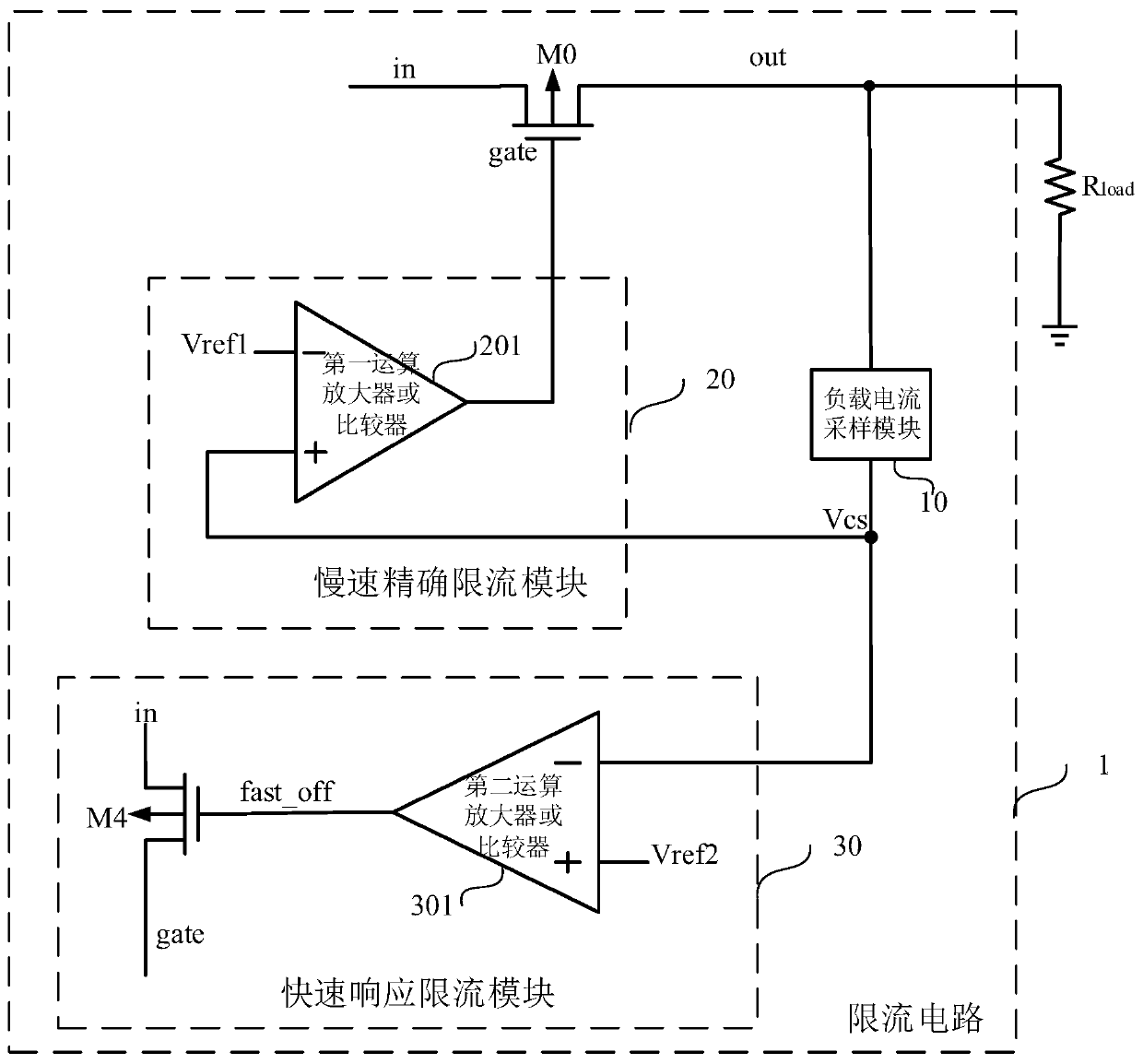
[0046] The slow and precise c...


PUM


Abstract

The invention relates to a current limiting circuit and a current limiting method, and belongs to the field of integrated circuits, which can realize a fast and accurate current limiting function, andcan be implemented in a low voltage standard CMOS process and a high voltage BCD process. The current limiting circuit includes a load current sampling module for sampling a load current of a power switch tube, converting the sampled load current into a voltage, and inputting the converted voltage to a slow and precise current limiting module and a fast responding current limiting module; the slow and precise current limiting module configured to control a gate voltage of the power switch tube to limit the load current to a preset current limit threshold when the converted voltage is higher than a first reference voltage; and the fast responding current limiting module configured to control a gate voltage of the power switch tube to quickly respond and limit current to the load current when the converted voltage is higher than a second reference voltage, wherein the first reference voltage is less than the second reference voltage.

Description

technical field [0001] The present disclosure relates to the field of integrated circuits, and in particular, to a current limiting circuit and a current limiting method. Background technique [0002] The power distribution switching circuit with current limiting function can distribute power for devices such as tablets, multimedia players, Bluetooth speakers, and other devices, and provide current limiting protection for switching regulators. However, in the existing power distribution switch circuit with current limiting function, the current limiting response speed is very slow when the device is short-circuited instantaneously, so that there will be a large peak current at the moment of short-circuit, which may cause potential damage to the switching regulator. risk. Although the Chinese patent application with the publication number CN102769281A discloses a fast-response current-limiting protection circuit, it needs to add a charge pump circuit, which is not conducive ...

Claims


Application Information

Patent Timeline
Patent Type & Authority Patents(China)
IPC IPC(8): H02H9/02
CPCH02H9/025
Inventor 张纯林彭祥
Owner ACTIONS ZHUHAI TECH CO
Why Eureka
Try Eureka