
Ventilation and heat dissipation structure of high voltage switch cabinets

A high-voltage switchgear, ventilation and heat dissipation technology, applied in the cooling/ventilation of substation/switchgear, details of substation/switch layout, electrical components, etc., can solve the problems of circuit components, no ventilation and heat dissipation structure, and influence on line power. Achieve the effect of preventing rainwater from entering and excellent heat dissipation effect

Inactive Publication Date: 2019-02-05
江苏信旺电气有限公司
View PDF0 Cites 1 Cited by
  • Summary
  • Abstract
  • Description
  • Claims
  • Application Information

AI Technical Summary

Problems solved by technology

[0003] The existing high-voltage switchgear used outdoors has been placed outdoors for a long time. Due to the influence of the environment, dust often enters and accumulates. If the dust accumulates seriously, it enters the inner cavity of the high-voltage switchgear and will affect circuit components. Moreover, the existing high-voltage switchgear works for a long time without an independent ventilation and heat dissipation structure, which leads to the inability to dissipate the heat of the high-voltage switchgear, thereby affecting the power of its lines

Method used


Image

  • Ventilation and heat dissipation structure of high voltage switch cabinets
  • Ventilation and heat dissipation structure of high voltage switch cabinets
  • Ventilation and heat dissipation structure of high voltage switch cabinets

Examples


Embodiment Construction

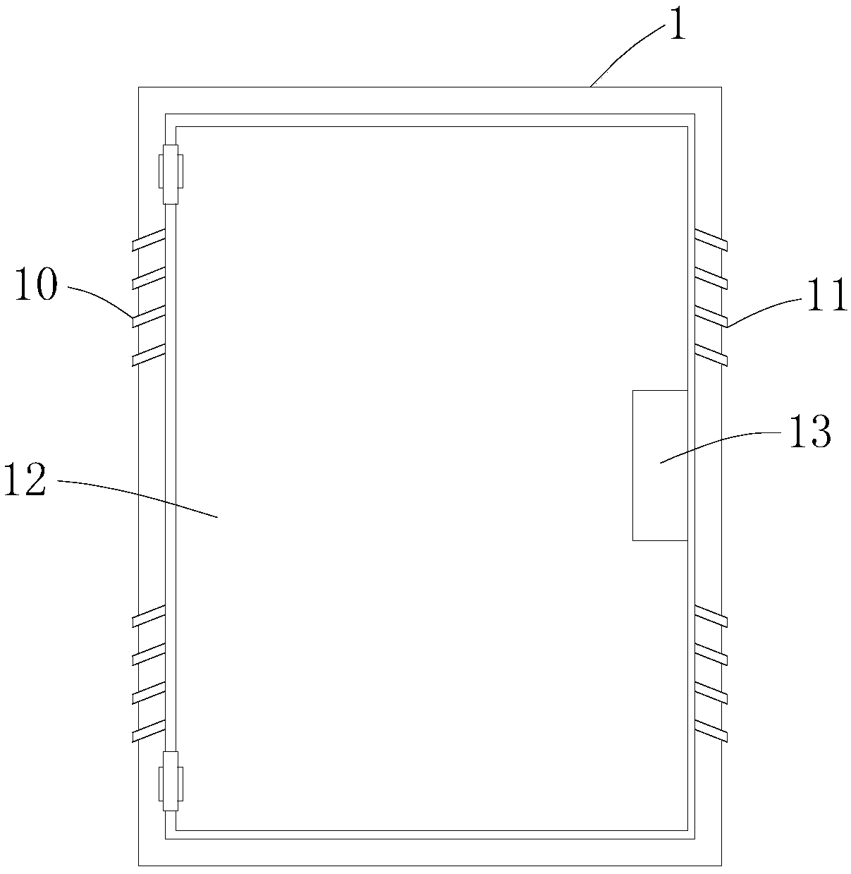
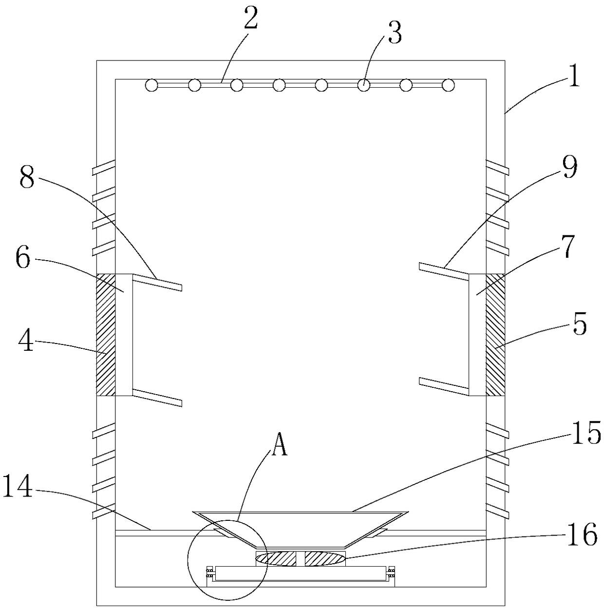
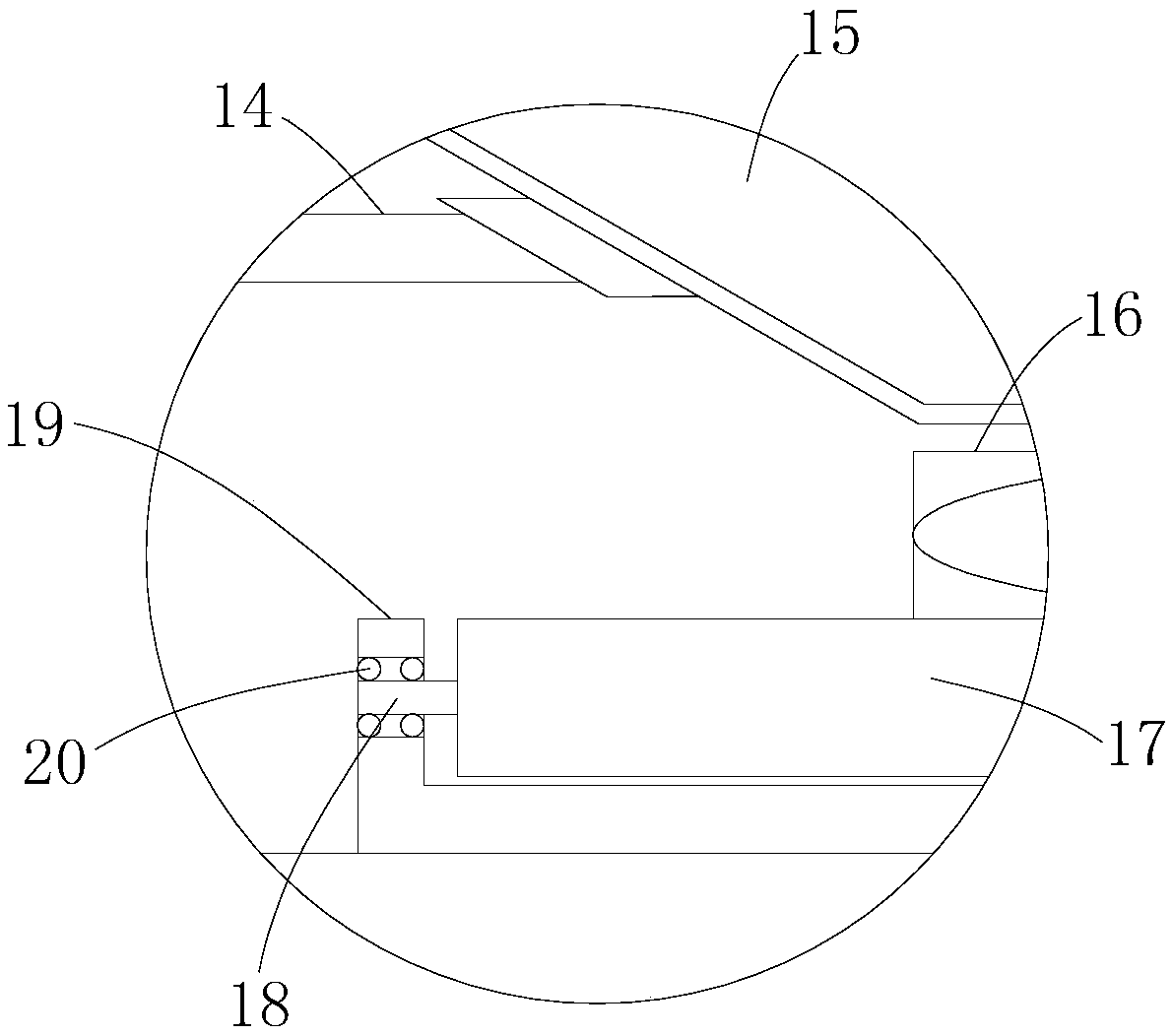
[0022] like Figure 1-4 As shown, the present invention provides a technical solution: a ventilation and heat dissipation structure of a high-voltage switchgear, including a switchgear body 1, a left rubber pad 4, a right rubber pad 5, an air induction bucket 15, an exhaust fan 16, and a left rubber pad 4 It is located at the left middle position of the inner wall of the switch cabinet body 1, the right rubber pad 5 is located at the right middle position of the inner wall of the switch cabinet body 1, the air induction bucket 15 is located at the bottom of the inner cavity of the switch cabinet body 1, and the exhaust fan 16 is located at the air induction bucket 15 The bottom of the switchgear body 1 is provided with a through groove in the middle of the left and right sides, the left rubber pad 4 is arranged in the through groove on the left side of the switchgear body 1, and the left rubber pad 4 is arranged in the through groove on the right side of the switchgear body 1. ...


PUM


Abstract

The invention relates to the technical field of high voltage switch cabinets, and discloses a ventilation and heat dissipation structure of high voltage switch cabinets. The structure includes a switch cabinet body, a left rubber pad, a right rubber pad, an air-leading bucket and an exhaust fan; the left rubber pad is located in the middle position on the left side of the inner wall of the switchcabinet body; and the right rubber pad is located in the middle position on the right side of the inner wall of the switch cabinet body. Through the arrangement of left and right slotting on the leftand right sides of the inner walls of the switch cabinet body, effects of natural ventilation of the switch cabinet body can be realized; through the installation of a first and second blower on the left and right sides of the inner walls of the switch cabinet body, fresh air can be absorbed from outside to discharge to the inner cavity of the switch cabinet body; through the inclined arrangementof a wind-guiding plate I and a wind-guiding plate II, the direction of horizontal blowing can be changed, no dead angle blowing of the inner cavity of the switch cabinet body can be realized, and compared with traditional ventilation and heat dissipation structures of high voltage switch cabinets, the structure is better in heat dissipation effect.

Description

technical field [0001] The invention relates to the technical field of high-voltage switch cabinets, in particular to a ventilation and heat dissipation structure for high-voltage switch cabinets. Background technique [0002] High-voltage switchgear refers to the role of on-off, control or protection in power system power generation, transmission, distribution, power conversion and consumption. High-voltage switchgear is used as electrical products with a voltage level of 3.6kV ~ 550kV, and high-voltage isolating switches There are several categories such as grounding switch, high-voltage load switch, high-voltage automatic reclosing and sectionalizer, high-voltage operating mechanism, high-voltage explosion-proof power distribution device and high-voltage switchgear. The switchgear has functions such as overhead incoming and outgoing lines, cable incoming and outgoing lines, and bus connection. It is mainly applicable to various places such as power plants, substations, pe...

Claims


Application Information

Patent Timeline
Patent Type & Authority Applications(China)
IPC IPC(8): H02B1/56H02B1/28H02B1/30
CPCH02B1/565H02B1/28H02B1/30
Inventor 刘旺
Owner 江苏信旺电气有限公司
Learn More