
Transparent LCD display panel

A transparent liquid crystal display, panel technology, applied in the direction of instruments, nonlinear optics, optics, etc., can solve the problem that the display panel cannot display the background behind the display panel, etc.

Active Publication Date: 2020-09-08
HUIZHOU CHINA STAR OPTOELECTRONICS TECHNOLOGY CO LTD
View PDF5 Cites 0 Cited by
  • Summary
  • Abstract
  • Description
  • Claims
  • Application Information

AI Technical Summary

Problems solved by technology

[0005] In view of the technical problem that the display panel in the prior art is non-transparent and cannot present the background behind the display panel, the present invention provides a transparent liquid crystal display panel to solve the technical problem in the prior art

Method used


Image

  • Transparent LCD display panel
  • Transparent LCD display panel

Examples


Embodiment Construction

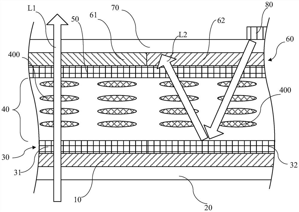
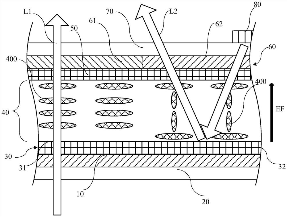
[0029] Please refer to figure 1 The transparent liquid crystal display panel of the present invention comprises: a glass substrate 10, a first polarizer 20, a first transparent electrode plate 30, a second transparent electrode plate 50, a liquid crystal layer 40, a color filter substrate 60, a second polarizer 70, and a light emitting diode unit 80 .

[0030] The first polarizer 20 has light transmittance and is disposed under the glass substrate 10 .

[0031] The first transparent electrode plate 30 is disposed above the glass substrate 10 and includes a translucent region 31 and a reflective region 32 , the transmissive region 31 is transmissive, and the reflective region 32 is reflective.

[0032] The second transparent electrode plate 50 has light transmittance and is opposite to the first transparent electrode plate 30 . In addition, the second transparent electrode plate 50 can be used as a common electrode.

[0033] The liquid crystal layer 40 is disposed between th...


PUM


Abstract

Disclosed is a transparent liquid crystal display panel, comprising a glass substrate (10), a first polarized plate (20), a first transparent electrode plate (30), a second transparent electrode plate (50), a liquid crystal layer (40), a colored light filter substrate (60), a second polarizer (70) and a light emitting diode unit (80). The first transparent electrode plate (30) has a light transmitting region (31) and a reflecting region (32). The colored light filter substrate (60) has a colorless part (61) corresponding to the light transmitting region (31) and a colored part (62) corresponding to the reflecting region (32). Light emitted from the light emitting diode unit (80) is reflected through the reflecting region (32) to display an image; and external light passes through the light transmitting region (31) and the colored part (62).

Description

technical field [0001] The invention relates to a transparent liquid crystal display panel, which can present the image of the display panel and the background behind the display panel simultaneously. Background technique [0002] Display panels in the prior art are generally opaque. For example, a backlight module is generally arranged on a liquid crystal display panel. through the light to display the image. Since the backlight module is opaque, viewers cannot see objects or scenes behind the display panel through the screen of the display panel, so the traditional display panel is opaque. [0003] Although newer organic light emitting diode display panels have self-illumination characteristics and omit the backlight module, a metal plate for reflecting light is generally provided on the back of the OLED display panel, and the metal plate is also opaque. Therefore, viewers also cannot see objects or scenes behind the display panel through the OLED display panel. [0004...

Claims


Application Information

Patent Timeline
Patent Type & Authority Patents(China)
IPC IPC(8): G02F1/1343G02F1/1335G02F1/13357
CPCG02F1/133514G02F1/133528G02F1/133603G02F1/134309G02F1/133302G02F1/133531
Inventor 陈俊吉
Owner HUIZHOU CHINA STAR OPTOELECTRONICS TECHNOLOGY CO LTD
Learn More