An automatic compensation device and method for time delay deviation in optical fiber time transmission

A technology of time transfer and automatic compensation, applied in time division multiplexing systems, electrical components, multiplexing communications, etc. , to achieve high adaptability and flexibility, and improve the effect of optical fiber time transfer accuracy

Active Publication Date: 2021-06-01
NAT TIME SERVICE CENT CHINESE ACAD OF SCI
View PDF6 Cites 0 Cited by
  • Summary
  • Abstract
  • Description
  • Claims
  • Application Information

AI Technical Summary

Problems solved by technology

[0003] In optical fiber time transfer, laser signals of two different wavelengths are often used in the same optical fiber for two-way time signal transmission, and high-precision time transfer is achieved through two-way time comparison; due to the different wavelengths of lasers used to transmit two-way time signals, the two-way time The transmission delay of the signal in the optical fiber link is different, which introduces the delay deviation, which will eventually affect the accuracy of the optical fiber time transfer; and the delay deviation will change with the change of the optical fiber link, and it is difficult to adjust the value by manual preset. Compensation makes it difficult to improve the accuracy of optical fiber time transfer, and requires an automatic compensation device and method for time delay deviation

Method used


Image

  • An automatic compensation device and method for time delay deviation in optical fiber time transmission
  • An automatic compensation device and method for time delay deviation in optical fiber time transmission
  • An automatic compensation device and method for time delay deviation in optical fiber time transmission

Examples


Embodiment

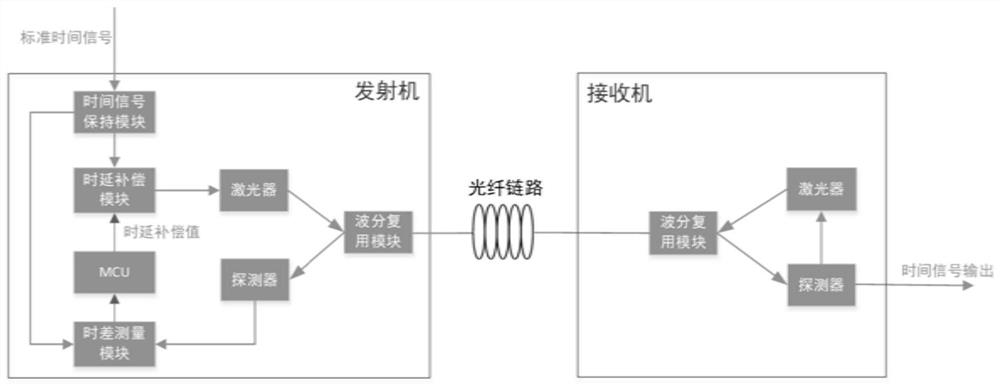
[0043] see figure 1 , a method for automatically compensating time delay deviations of two-way different wavelengths in optical fiber time transfer of the present invention, specifically comprising the following steps:

[0044] 1) Build an optical fiber time transfer system, connect the transmitter and receiver with an optical fiber with a length of about 50km (the length of the optical fiber link can be any length not exceeding 100km), and measure the time of two laser signals with different wavelengths wavelength, and record it, including the following steps:

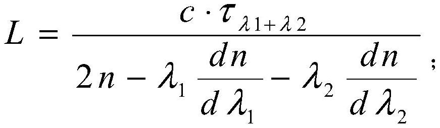
[0045] 1.1) Use a high-precision wavelength meter to measure the wavelength of the laser signal of the optical fiber time transfer transmitter, which is λ 1 =1543.73nm;

[0046] 1.2) Measure the wavelength of the laser signal of the receiver with a high-precision wavelength meter, and record it as λ 2 = 1542.94 nm.

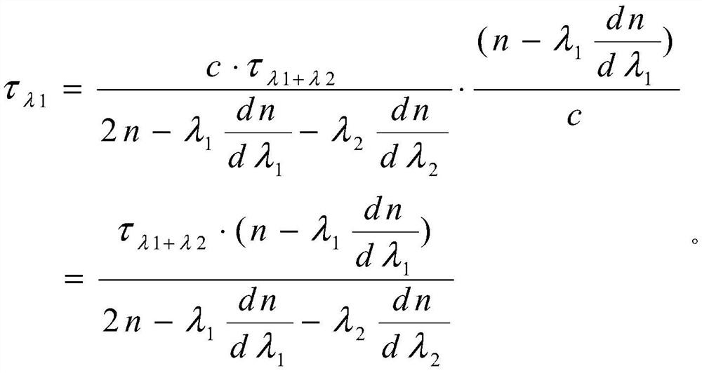
[0047] 2) Measuring the round-trip delay difference of the time signal transmitted in the same opt...


PUM


Abstract

The invention discloses an automatic compensation device and method for time delay deviation in optical fiber time transmission, comprising: a time difference measurement module and a time delay compensation module are arranged in the transmitting end; the time difference measurement module is used to receive the standard time signal sent by the transmitting end And the returned time signal and output the time difference value of the two; the time delay compensation module is used to obtain the time delay compensation value according to the time difference value obtained by the time difference measurement module and compensate the standard time signal sent by the transmitter; through the time difference measurement The module calculates and obtains the round-trip delay difference of two-way different wavelength signal transmission in the preset same optical fiber link; calculates the delay compensation value through the obtained round-trip delay difference; according to the obtained delay compensation value, through the delay compensation The module automatically compensates the standard time signal. The invention can automatically compensate the time delay deviation when the bidirectional time signal is transmitted in the optical fiber link in real time, and can improve the accuracy of optical fiber time transmission.

Description

technical field [0001] The invention belongs to the technical field of optical fiber time service synchronization, in particular to an automatic compensation device and method for time delay deviation in optical fiber time transmission. Background technique [0002] With the development of science and technology, in the fields of aerospace, radar synchronization, cutting-edge weapon control, high-speed communication, and deep space exploration, higher and higher requirements for timing accuracy have been put forward. Traditional timing methods, such as long-wave timing and satellite timing, can only achieve nanosecond timing accuracy, while optical fiber time transfer technology can achieve timing accuracy better than 100 picoseconds. Optical fiber time transfer technology has the advantages of high timing accuracy and low equipment price, and has broad application prospects. [0003] In optical fiber time transfer, laser signals of two different wavelengths are often used ...

Claims


Application Information

Patent Timeline
Patent Type & Authority Patents(China)
IPC IPC(8): H04J3/06
CPCH04J3/0682
Inventor 赵侃陈法喜张首刚刘涛
Owner NAT TIME SERVICE CENT CHINESE ACAD OF SCI
Why Eureka
Try Eureka