A method for estimating the round-trip delay difference of optical fiber time transfer under temperature change

A technology of time transfer and temperature change, applied in the field of electrical communication, can solve problems such as difficult to complete, difficult to apply in a large range, impossible to data, etc., to achieve the effect of improving the transmission accuracy, expanding the applicable environment, and improving the timing accuracy.

Active Publication Date: 2022-01-11
NAVAL UNIV OF ENG PLA
View PDF8 Cites 0 Cited by
  • Summary
  • Abstract
  • Description
  • Claims
  • Application Information

AI Technical Summary

Problems solved by technology

Compared with the three, the transmission accuracy of SDH network is low, the cost of using TDM technology is high, and it is difficult to apply in a large range
[0006] To sum up, the problems existing in the existing technology are: the existing cost, technology maturity, and accuracy are applicable to the optical fiber timing method of large-scale networking, which is the loopback transfer method based on WDM technology, but the existing optical fiber transfer technology is usually It is only applied in a constant temperature environment in the laboratory, and does not consider the change in delay difference under the condition of temperature change. At the same time, there is no method for estimating the round-trip delay difference in the environment of temperature change in the prior art, which affects the actual laying to a certain extent. The timing accuracy of the optical cable network, so this factor is an urgent consideration for the practical use of optical fiber timing
However, even if it is just to keep measuring the temperature of the fiber surface and transmit the test data to the delay difference calculation part, it is already difficult to complete
At the same time, the error in estimating the core temperature from the surface temperature of the optical fiber is relatively large. Considering that the actual environment is often transmitted through the optical cable network, the temperatures of the optical cable network, optical fiber, and fiber core are different. It can be seen that the required data can be directly measured. Basically impossible, so no better method has been proposed

Method used


Image

  • A method for estimating the round-trip delay difference of optical fiber time transfer under temperature change
  • A method for estimating the round-trip delay difference of optical fiber time transfer under temperature change
  • A method for estimating the round-trip delay difference of optical fiber time transfer under temperature change

Examples


Embodiment 1

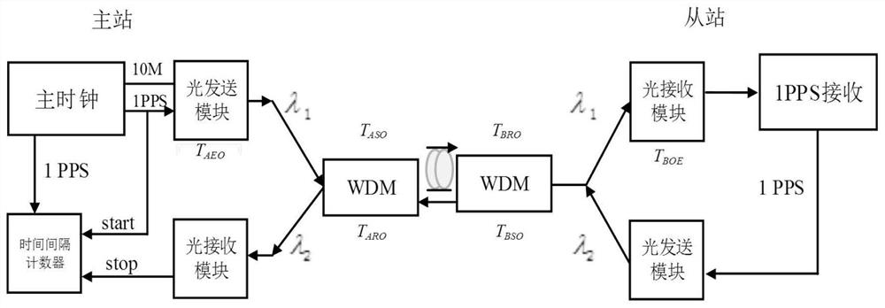
[0055] 1. Existing WDM-based loopback method:

[0056] Existing WDM-based loopback method, such as figure 2 shown;

[0057] The time measured by the time interval counter of the master station is:

[0058] T=T AEO +T ASO +T ARO +T AOE +T AB +T BA +T BSO +T BEO +T BOE +T BRO (1.1)

[0059] T AEO Indicates the electro-optical delay of the central station, and the corresponding photoelectric delay is T AOE ;

[0060] T ASO Indicates the delay of optical processing sent by the central station; T BSO Indicates the transmission delay of the terminal station;

[0061] T BEO Indicates the photoelectric delay of the terminal station, and the corresponding electro-optic delay is T BOE ;

[0062] T BRO Indicates the receiving delay of the optical path of the terminal station; T ARO Indicates the receiving optical path delay of the central station;

[0063] T AB Indicates the fiber transmission delay from the central station to the terminal station, and the fiber...


PUM


Abstract

The invention belongs to the technical field of electrical communication, and discloses a method and system for estimating the round-trip time delay difference of optical fiber time transmission under temperature changes. The method for estimating round-trip time delay difference of optical fiber time transmission under temperature changes includes: The device calibrates the relatively fixed delay generated by the hardware at both ends; subtract the hardware delay obtained in step 1 from the total loop delay to obtain the transfer delay sum; according to the clear correspondence between the transfer delay sum and temperature Reversely deduce the real-time temperature; calculate the transfer delay difference according to the corresponding relationship between temperature and transfer delay difference; calculate the real-time single-phase delay value. The invention provides a method capable of accurately estimating the round-trip time delay difference even in a temperature-changing environment, thereby greatly saving costs, improving the accuracy of optical fiber time transmission, and expanding its applicable environment.

Description

technical field [0001] The invention belongs to the technical field of electric communication, and in particular relates to a method for estimating round-trip delay difference of optical fiber time transfer under temperature change. Background technique [0002] At present, the closest existing technology: with the advancement of science and technology, the current stability of the optical frequency atomic clock reaches 10 -18 , which has the highest measurement accuracy among the seven SI units. However, a single atomic clock cannot achieve large-scale time service, and time transfer and comparison between long-distance clocks not only helps to improve the accuracy and stability of the clock source, but also improves the overall performance and redundancy of the clock group. Significance. Therefore, how to transmit high-precision time-frequency information to each client has become an important topic in this field. [0003] Due to its unique advantages such as low loss, ...

Claims


Application Information

Patent Timeline
Patent Type & Authority Patents(China)
IPC IPC(8): H04B10/071
CPCH04B10/071
Inventor 吴苗梁益丰李方能许江宁于燕婷陈丁
Owner NAVAL UNIV OF ENG PLA
Why Eureka
Try Eureka