
A car radiator with shock absorbing structure

A technology for automobile radiators and heat sinks, which is applied to the cooling combination of power plants, vehicle components, machines/engines, etc. It can solve the problems of affecting the flow of coolant, reducing the cooling effect of the engine, and affecting the use of users, etc., to achieve Scientific and reasonable structure, remarkable heat dissipation effect, safe and convenient use

Active Publication Date: 2019-12-24
郴州市中马汽车空调有限公司
View PDF8 Cites 0 Cited by
  • Summary
  • Abstract
  • Description
  • Claims
  • Application Information

AI Technical Summary

Problems solved by technology

[0003] The present invention provides a car radiator with a shock absorbing structure, which can effectively solve the problem of the above-mentioned background technology that often only includes basic components for heat dissipation of the car engine, a large amount of vibration generated when the engine is working, and different road conditions when the car is running. Vibration can easily cause the pressure on one side of the heat sink in the radiator to be greater than the pressure on the other side of the heat sink. After a period of operation, the heat sink is prone to burst and other phenomena, which will eventually lead to damage to the car radiator and affect the user's perception of the car. In use, and when the existing car radiator is used, the interior of the radiator fin of the car radiator is prone to scale adhesion after a long time, and after a period of time, the radiator fin inside the radiator is prone to blockage, which affects cooling The liquid flows inside the heat sink in the radiator, which will eventually lead to a gradual decrease in the heat dissipation effect of the overall car radiator, a decrease in the cooling effect on the engine, and problems affecting the use of the car by users.

Method used


Image

  • A car radiator with shock absorbing structure
  • A car radiator with shock absorbing structure
  • A car radiator with shock absorbing structure

Examples


Embodiment

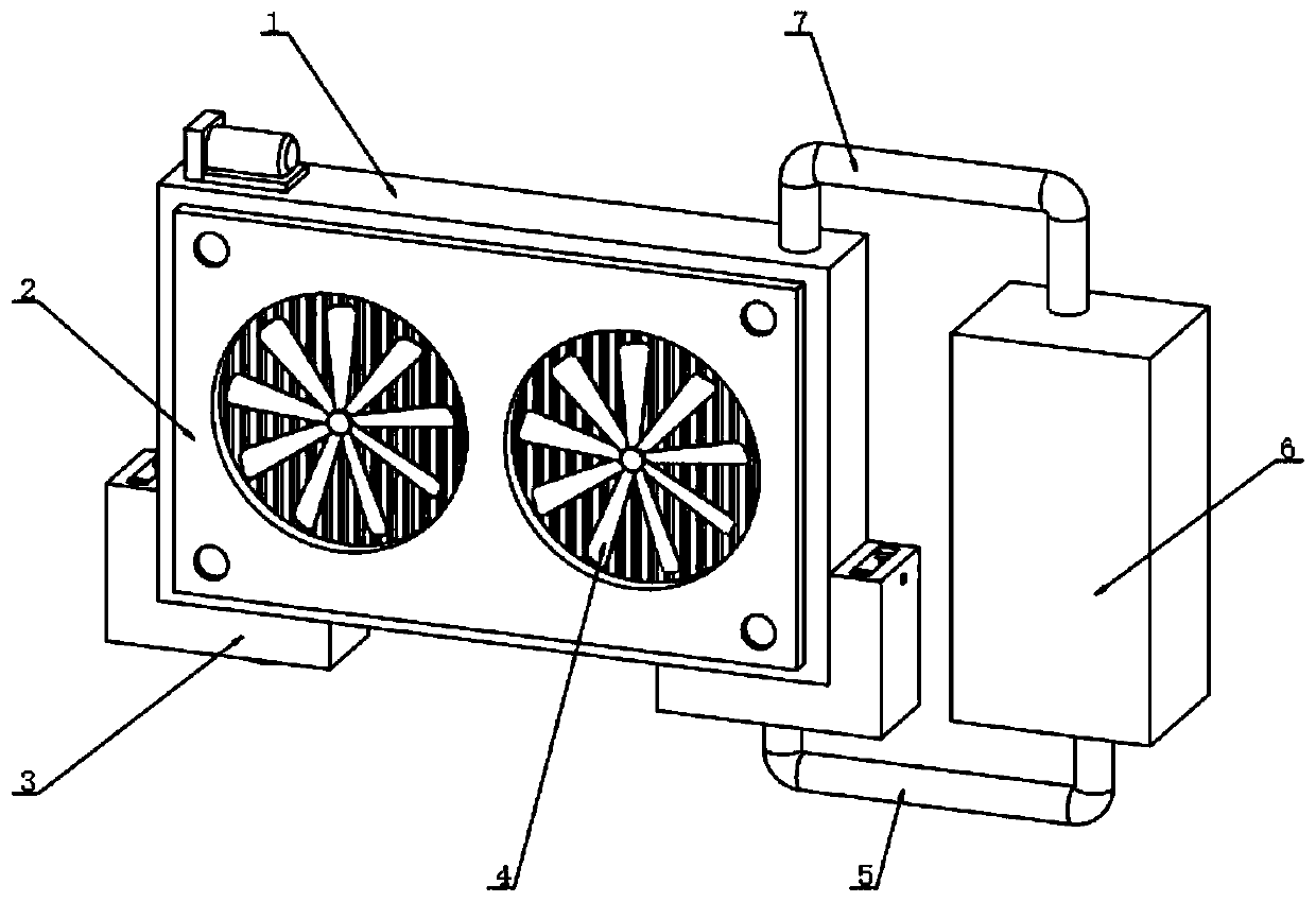
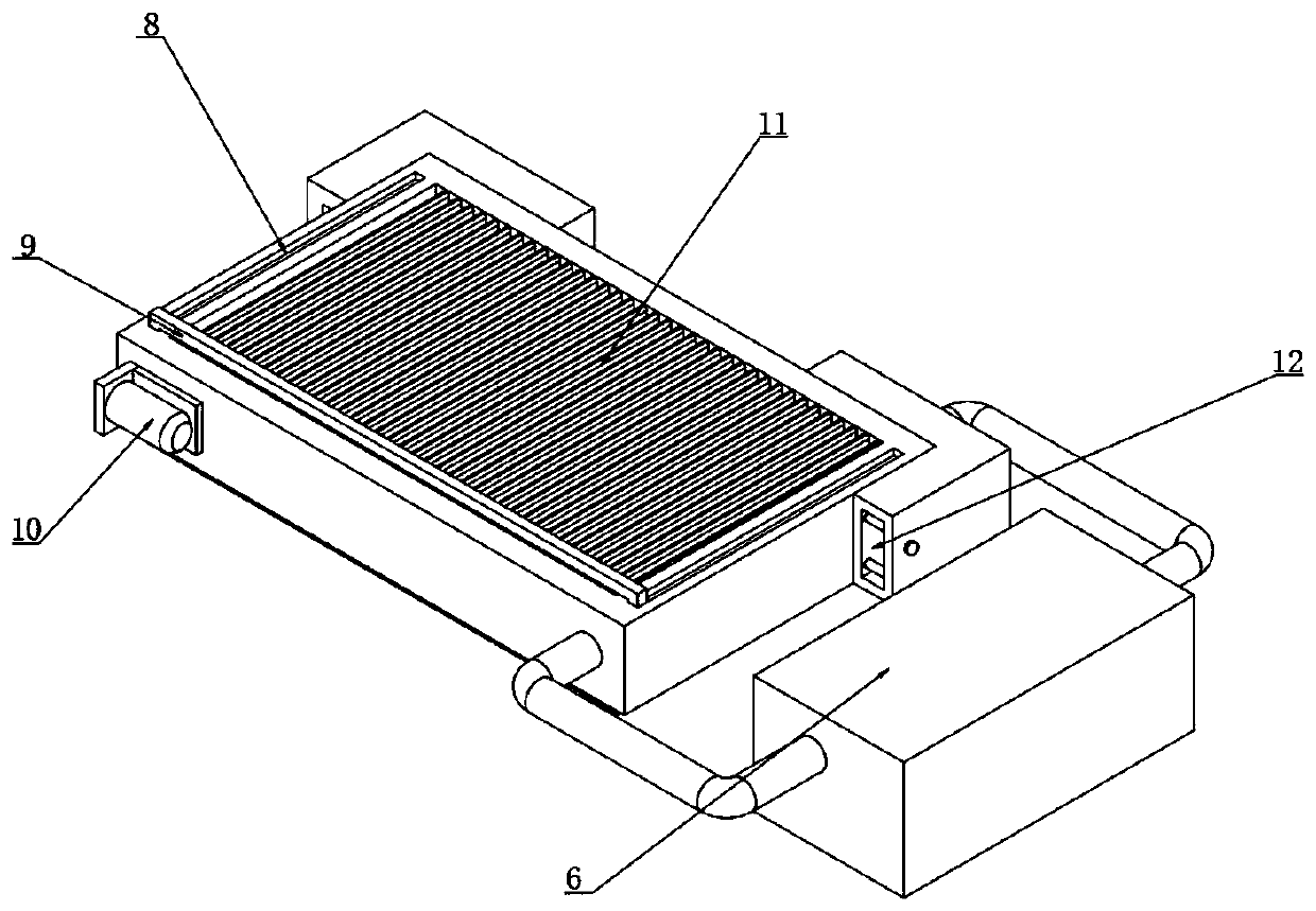
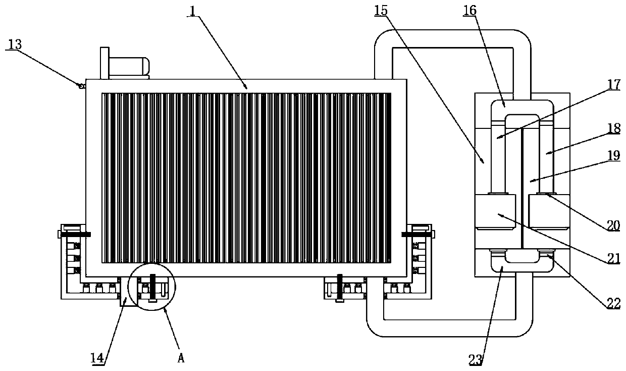
[0029] Example: such as Figure 1-6 As shown, the present invention provides a technical solution for an automobile radiator with a shock absorbing structure. A car radiator with a shock absorbing structure includes a heat sink mounting seat 1, and one side of the heat sink mounting seat 1 is fixedly connected with a fan for mounting. Plate 2, in order to facilitate the disassembly and installation between the fan mounting plate 2 and the heat sink mounting seat 1, the fan mounting plate 2 and the heat sink mounting seat 1 are connected by bolts, in order to prevent the heat sink mounting seat 1 from The outer side of the radiator is corroded and damaged, the outer side of the cooling fin mounting base 1 is coated with anti-rust paint, one side of the fan mounting plate 2 is symmetrically embedded with a cooling fan 4, and the top inner wall of the cooling fin mounting base 1 is evenly connected with a cooling fin 11, The bottom side of the heat sink mounting seat 1 is symmetr...


PUM


Abstract

The invention discloses an automobile radiator with a shock absorbing structure. A cooling fin installing base is included; one side of the cooling fin installing base is fixedly connected with a faninstalling plate; cooling fans are symmetrically embedded in and installed in one side of the fan installing plate; and the inner wall of the top of the cooling fin installing base is uniformly connected with cooling fins. The automobile radiator with the shock absorbing structure is scientific and reasonable in structure, and safe and convenient to use; after cooling an automobile, due to runningof a water sucking pump, a cooling fin cleaning agent in a second storing bin can be conveyed into the cooling fins, and therefore the interiors of the cooling fins installed in the cooling bin installing base can be cleaned, and it can be avoided that scale is accumulated in the cooling fins, and consequently the cooling fins are blocked; and due to shock absorbing installing bases symmetricallyinstalled at the bottom of the cooling fin installing base, shock absorbing protection can be performed on the automobile radiator, and it is avoided that waggle generated by the automobile is transmitted to the automobile radiator, and consequently the interior of the automobile radiator is vibrated.

Description

technical field [0001] The invention relates to the technical field of automobile radiators, in particular to an automobile radiator with a shock absorbing structure. Background technique [0002] A car is a non-track-bearing vehicle driven by power and has four or more wheels. It is mainly used to carry people or goods, and tow vehicles that carry people or goods. With the development of science and technology, cars have gradually appeared in In people's life, the operation of a car is to generate power through the combustion of gasoline or diesel in the engine to drive the car to run. The engine is mainly composed of 2 major mechanisms and 5 major systems: crank connecting rod mechanism, valve mechanism, cooling system, and fuel supply. system, lubrication system, ignition system, and starting system. The cooling system is generally composed of water tanks, water pumps, radiators, fans, thermostats, water temperature gauges, and water discharge switches. Automobile radiato...

Claims


Application Information

Patent Timeline
Patent Type & Authority Patents(China)
IPC IPC(8): F01P11/00F01P11/02F01P11/06F01P5/10F01P3/18B60K11/04
CPCB60K11/04F01P3/18F01P5/10F01P11/00F01P11/0276F01P11/06F01P2011/061F01P2011/063
Inventor 李建国张大喜张悦
Owner 郴州市中马汽车空调有限公司
Learn More