
Adjustable fixing mechanism of windproof tower crane base

A fixed mechanism and adjustable technology, applied in the direction of cranes, transportation and packaging, etc., can solve the problems of waste of resources, removal of the base, difficult handling, shaking of the tower crane, etc., and achieve the effect of easy calibration of the direction of the tower body, convenient operation and avoiding wear and tear

Inactive Publication Date: 2019-01-29
苏州南坡之林企业孵化管理有限公司
View PDF8 Cites 0 Cited by
  • Summary
  • Abstract
  • Description
  • Claims
  • Application Information

AI Technical Summary

Problems solved by technology

[0002] With the development of society, the construction industry has advanced by leaps and bounds in recent years. All high-rise buildings will use tower cranes. A solid base must be built for erecting tower cranes. Most of the existing tower crane bases are fixedly connected to the foundation. At present, the height of tower cranes is increasing year by year. Wind resistance has become an important factor affecting the stability of the tower crane. When the tower crane is subjected to a large wind force, it is easy to cause the tower crane itself to shake
In order to ensure that the base is solid, most of the bases are fixed by concrete pouring at present, but it is very easy to cause waste of resources and cause great difficulties in dismantling the base and handling

Method used


Image

  • Adjustable fixing mechanism of windproof tower crane base
  • Adjustable fixing mechanism of windproof tower crane base
  • Adjustable fixing mechanism of windproof tower crane base

Examples


Embodiment Construction

[0015] The present invention will be further described below with reference to the drawings and specific embodiments.

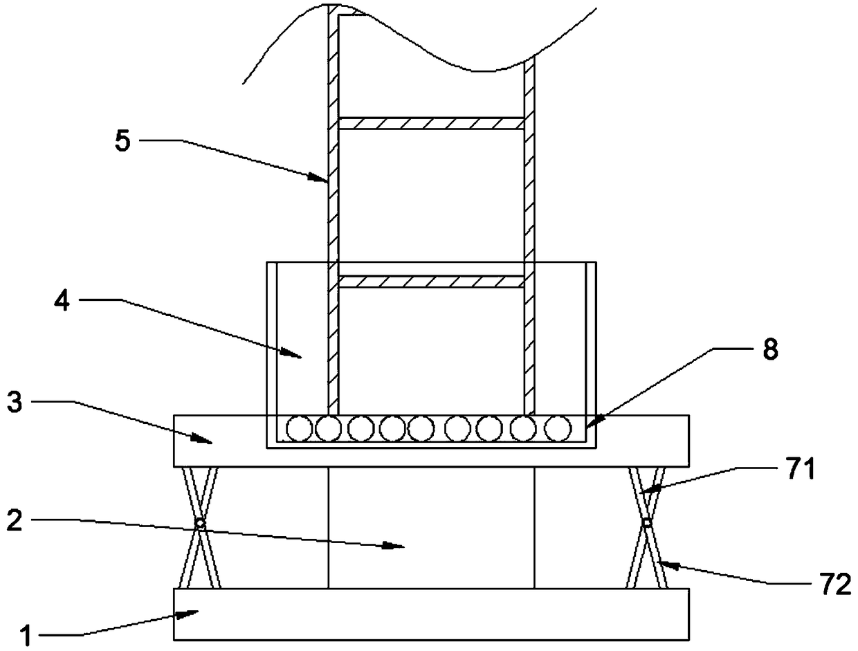
[0016] Such as figure 1 As shown, the adjustable fixing mechanism of the base of the windbreak tower crane includes a base 1, a mounting column 2, a bottom plate 3, a base 4, and a tower body 5 sequentially arranged from bottom to top, and the base 1 and the bottom plate 3 are connected around by studs. A first connecting rod 71 and a second connecting rod 72 are intersected between the top of the base 1 and the bottom of the base 4, and the intersection of the first connecting rod 71 and the second connecting rod 72 is movably connected by a pin. Both ends of the first pull rod 71 and the second pull rod 72 are connected to the bottom plate 3 and the base 1 by studs, and a rotating mechanism 8 for driving the tower body 5 to rotate is arranged between the bottom plate 3 and the tower body 5.

[0017] When the wind resistance of the site environment is small or th...


PUM


Abstract

The invention discloses an adjustable fixing mechanism of a windproof tower crane base. The adjustable fixing mechanism of the windproof tower crane base sequentially comprises a base, an installationcolumn, a base plate, a foundation seat and a tower body from bottom to top. The peripheries of the base and the base plate are connected through bolts. First connection rods and second connection rods are arranged between the peripheries of the top of the base and the bottom of the foundation seat in an intersecting manner. The intersection portions between each pair of the first connection rodand the second connection rod are movably connected through a pin shaft. The two ends of each first connection rod and the two ends of each second connection rod are connected with the base plate andthe base through double-screw bolts. A rotating mechanism used for driving the tower body to rotate is arranged between the base plate and the tower body. When the on-site environment wind resistanceis small or the height of the tower crane is small, the first connection rods and the second connection rods can be eliminated, and the first connection rods and the second connection rods are foldedthrough the pin shafts, so that integrated collection is convenient. When the on-site environment wind resistance is large or the height of the tower crane is large, the first connection rods and thesecond connection rods are connected with the base plate and the base in the threaded manner, and therefore the stability of the base is improved.

Description

Technical field [0001] The invention relates to an adjustable fixing mechanism of a windproof tower crane base. Background technique [0002] With the development of society, the construction industry has been advancing by leaps and bounds in recent years. All high-rise buildings will use tower cranes. To erect tower cranes, a solid base must be built. Most of the existing tower crane bases are fixedly connected to the foundation, and the height of the tower crane is increasing year by year. Wind resistance has become an important factor affecting the stability of the tower crane. When the tower crane is subjected to a large wind, it is easy to cause the tower crane itself to shake. In order to ensure that the base is solid, most of the bases are fixed by concrete irrigation at present, but it is very easy to cause waste of resources and cause great difficulty in removing the base and handling. [0003] In view of this, overcoming the above-mentioned defects in the prior art is an...

Claims


Application Information

Patent Timeline
Patent Type & Authority Applications(China)
IPC IPC(8): B66C23/62B66C23/84
CPCB66C23/62B66C23/84B66C2700/03
Inventor 孙土根季坤
Owner 苏州南坡之林企业孵化管理有限公司
Learn More