
Steel bar bender

A steel bar bending and steel bar technology, applied in the field of steel bar processing equipment, can solve the problems of high labor intensity of workers, and achieve the effect of simple structure and convenient use

Active Publication Date: 2019-01-29
浙江礼显试验仪器制造有限公司
View PDF6 Cites 7 Cited by
  • Summary
  • Abstract
  • Description
  • Claims
  • Application Information

AI Technical Summary

Problems solved by technology

[0003] When the existing steel bar bending machine is in use, the worker needs to place the steel bar to be processed on the workbench, clamp one end of the steel bar to one side of the movable bending pin on the turntable, and use the movable bending pin to rotate with the turntable. The force is used to achieve the purpose of bending the steel bar; the other end and the main body are clamped between the positioning block and the positioning pin to prevent the steel bar from moving during the bending process and affect the bending effect
[0004] In this process, workers are required to load the steel bars after each bending work of a steel bar is completed, and the labor intensity of the workers is high.

Method used


Image

  • Steel bar bender
  • Steel bar bender
  • Steel bar bender

Examples


Embodiment Construction

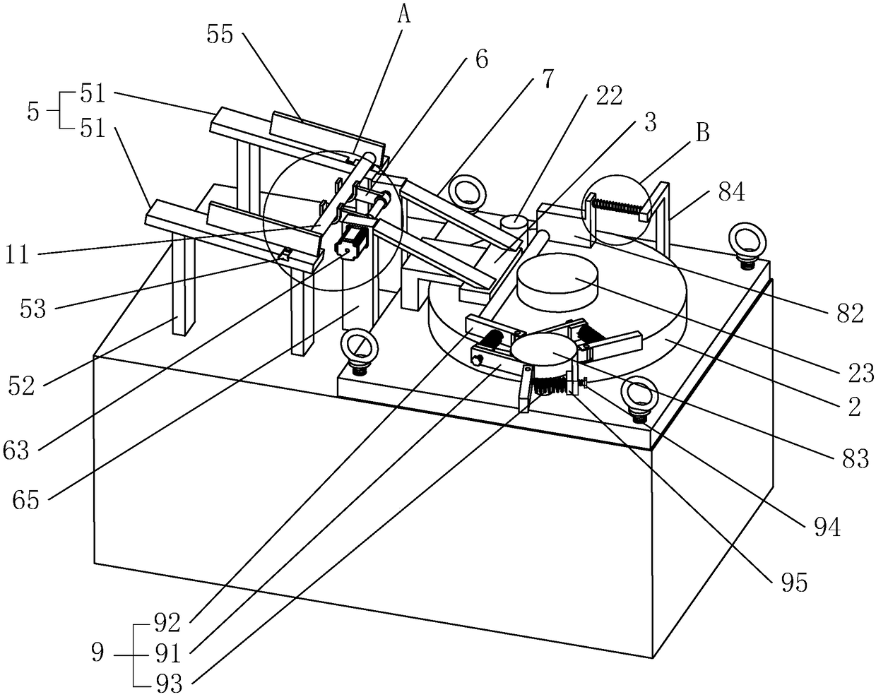
[0036] Such as figure 1As shown, a steel bar bending machine includes a workbench 1, a turntable 2 driven by a main motor inside the workbench 1 is provided on the surface of the workbench 1, a bending hole is eccentrically opened on the turntable 2, and a bending hole is inserted in the bending hole The movable bending pin 22 is provided with a positioning pin 23 at the center of the turntable 2, and a positioning block 3 is fixed on the workbench 1. The bottom surface of the positioning block 3 is located on the upper surface of the turntable 2. The surface of 23 forms a fixed opening for placing and fixing the steel bar 11 to be processed, and the movable bending pin 22 is located on the side of the steel bar 11 facing away from the positioning pin 23 .

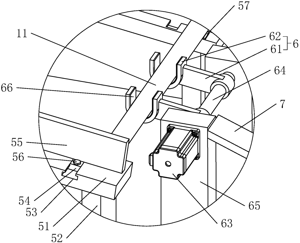
[0037] Such as figure 1 As shown, a feeding device is provided on the workbench 1, and the feeding device includes a storage rack 5, a feeding arm 6, a feeding motor 63 and a feeding slide rail 7 that are distributed in s...


PUM


Abstract

The invention relates to the technical field of steel bar machining equipment and discloses a steel bar bender. The steel bar bender comprises a workbench. The workbench is provided with a rotary table and a positioning block. The rotary table is eccentrically provided with a movable bending pin and concentrically provided with a positioning pin. The workbench is further provided with a feeding device. The feeding device comprises a storage frame, a feeding arm, a feeding motor and a feeding slide rail which are all sequentially arranged. The storage frame is arranged on the workbench. Steel bars are sequentially arranged on the storage frame. The feeding motor is arranged on the workbench. One end of the feeding slide rail is arranged near the feeding arm, and the other end of the feedingslide rail is arranged above the positioning block and the positioning pin. The feeding slide rail is obliquely and downwards arranged in the steel bar conveying direction. The feeding motor drives the feeding arm to rotate so that the steel bars on the storage frame can be sequentially sent onto the feeding slide rail. According to the steel bar bender, the feeding device is used for carrying out automatic feeding on the steel bars, the structure is simple, and the labor intensity of workers is reduced.

Description

technical field [0001] The invention belongs to the technical field of steel bar processing equipment, in particular to a steel bar bending machine. Background technique [0002] The steel bar bending machine is the equipment used to bend the steel bar so that the steel bar is suitable for actual needs. [0003] When the existing steel bar bending machine is in use, the worker needs to place the steel bar to be processed on the workbench, clamp one end of the steel bar to one side of the movable bending pin on the turntable, and use the movable bending pin to rotate with the turntable. The force is used to achieve the purpose of bending the steel bar; the other end and the main body are clamped between the positioning block and the positioning pin to prevent the steel bar from moving during the bending process and thus affect the bending effect. [0004] In this process, workers are required to load the steel bars after each bending work of a steel bar is completed, and the...

Claims


Application Information

Patent Timeline
IPC IPC(8): B21F1/00B21F23/00
CPCB21F1/00B21F23/00
Inventor 沈一炯
Owner 浙江礼显试验仪器制造有限公司
Learn More